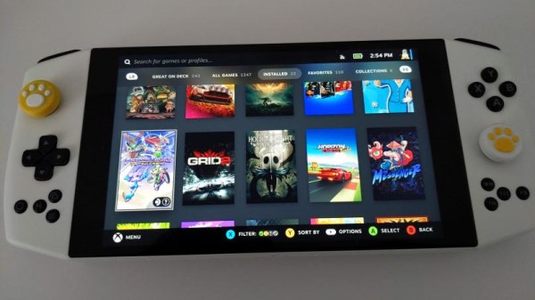
A Simple Guide To Bit Banged I2C On The 6502

We covered [Anders Nielsen]’s 65duino project a short while ago, and now he’s back with an update video showing some more details of bit-banging I2C using plain old 6502 assembly language.

Obviously, with such a simple system, there is no dedicated I2C interface hardware, so the programmer must take care of all the details of the I2C protocol in software, bit-banging it out to the peripheral and reading back the response one bit at a time.

The first detail to concern us will be the I2C addresses of the devices being connected to the bus and how low-level bit manipulation is used to turn the 7-bit I2C address into the byte being bit-banged. As [Anders] shows, setting a bit is simply a logical-OR operation, and resetting a bit is a simple logical-AND operation using the inversion (or one’s complement) bit to reset to form a bitmask. As many will already know, this process is necessary to code for a read or a write I2C operation. A further detail is that I2C uses an open-collector connection scheme, which means that no device on the bus may drive the bus to logical high; instead, they must release the drive by going to the high impedance state, and an external pull-up resistor will pull the bus high. The 6532 RIOT chip (used for I/O on the 65unio) does not have tristate control but instead uses a data direction register (DDR) to allow a pin to be an input. This will do the job just fine, albeit with slightly odd-looking code, until you know what’s going on.

From there, it’s a straightforward matter to write subroutines that generate the I2C start, stop, and NACK conditions that are required to write to the SSD1306-based OLED to get it to do something we can observe. From these basic roots, through higher-level subroutines, a complete OLED library in assembly can be constructed. We shall sit tight and await where [Anders] goes next with this!

We see I2C-connected things all the time, like this neat ATtiny85-based I2C peripheral, and whilst we’re talking about the SSD1306 OLED display controller, here’s a hack that shows just how much you can push your luck with the I2C spec and get some crazy frame rates.

Continue reading “A Simple Guide To Bit Banged I2C On The 6502”

Learning X86_64 Assembly By Building A GUI From Scratch

Some professional coders are absolutely adamant that learning to program in assembly language in these modern times is simply a waste of time, and this post is not for them. This is for the rest of us, who still think there is value in knowing at a low level what is going on, a deeper appreciation can be developed. [Philippe Gaultier] was certainly in this latter camp and figured the best way to learn was to work on a substantial project.

Now, there are some valid reasons to write directly in assembler; for example hand-crafting unusual code sequences for creating software exploits would be hindered by an optimising compiler. Creating code optimised for speed and size is unlikely to be among those reasons, as doing a better job than a modern compiler would be a considerable challenge. Some folks would follow the tried and trusted route and work towards getting a “hello world!” output to the console or a serial port, but not [Philippe]. This project aimed to get a full-custom GUI application running as a client to the X11 server running atop Linux, but the theory should be good for any *nix OS.

Hello World! In X11!

The first part of the process was to create a valid ELF executable that Linux would work with. Using nasm to assemble and the standard linker, only a few X86_64 instructions are needed to create a tiny executable that just exits cleanly. Next, we learn how to manipulate the stack in order to set up a non-trivial system call that sends some text to the system STDOUT.

To perform any GUI actions, we must remember that X11 is a network-orientated system, where our executable will be a client connected via a socket. In the simple case, we just connect the locally created socket to the server path for the local X server, which is just a matter of populating the sockaddr_un data structure on the stack and calling the connect() system call.

Now the connection is made, we can follow the usual X11 route of creating client ids, then allocating resources using them. Next, fonts are opened, and a graphical context is created to use it to create a window. Finally, after mapping the window, something will be visible to draw into with subsequent commands. X11 is a low-level GUI system, so there are quite a few steps to create even the most simple drawable object, but this also makes it quite simple to understand and thus quite suited to such a project.

We applaud [Phillip] for the fabulous documentation of this learning hack and can’t wait to see what’s next in store!

Not too long ago, we covered Snowdrop OS, which is written entirely in X86 assembly, and we also found out a thing or two about some oddball X86 instructions. We’ve also done our own Linux assembly primer.

Protect Vintage Gear With Easy Capacitor Reforming

Having acquired some piece of old electronic equipment, be it a computer, radio, or some test gear, the temptation is there to plug it in as soon as you’ve lugged it into the ‘shop. Don’t be so hasty. Those power supplies and analog circuits often have a number of old aluminium electrolytic capacitors of unknown condition, and bad things can happen if they suddenly get powered back up again. After a visual inspection, to remove and replace any with obvious signs of leakage and corrosion, those remaining may still not be up to their job, with the oxide layers damaged over time when sat idle, they can exhibit lower than spec capacitance, voltage rating or even be a dead short circuit. [TechTangents] presents for us a guide to detecting and reforming these suspect capacitors to hopefully bring them, safely, back to service once more.

Capacitor failure modes are plentiful

When manufactured, the capacitors are slowly brought up to operating voltage, before final encapsulation, which allows the thin oxide layer to form on the anode contact plate, this is an electrically driven chemical process whereby a portion of the electrolyte is decomposed to provide the needed oxygen ions. When operating normally, with a DC bias applied to the plates, this oxidation process — referred to as ‘self-healing’ — continues slowly, maintaining the integrity of the oxide film, and slowly consuming the electrolyte, which will eventually run dry and be unable to sustain the insulating oxide layer.

If left to sit un-powered for too long, the anodic oxide layer will decay, resulting in reduced operating voltage. When powered up, the reforming process will restart, but this will be in an uncontrolled environment, resulting in a lot of excess heat and gases being vented. It all depends on how thin the oxide layer got and if holes have started to form. That is, if there is any electrolyte left to react – it may already be far too late to rescue.

If the oxide layer is sufficiently depleted, the capacitor will start to conduct, with a resultant self-heating and runaway thermal decomposition. They can explode violently, which is why there are score marks at the top of the can to act as a weak point, where the contents can burst through. A bit like that ‘egg’ scene in Aliens!

Yucky leaky capacitor. Replace these! and clean-up that conductive goo too.

The ‘safe’ way to reform old capacitors is to physically remove them from the equipment, and apply a low, controlled voltage below the rated value to keep the bias current at a low value, perhaps just 2 mA. Slowly, the voltage can be increased to push the current back up to the initial forming level, so long as the current doesn’t go too high, and the temperature is within sensible bounds. The process ends when the applied voltage is at the rated value and the current has dropped off to low leakage values.

A word of warning though, as the ESR of the reformed caps could be a little higher than design, which will result in higher operating temperature and potentially increased ripple current in power supply applications.

We’re really glossing over this subject fast here, but [TechTangents] was kind enough to link to some fine capacitor-related reading for those who need a primer. Here is a US DoD handbook for reforming capacitors with advice on storage shelf life, some tech notes on using electrolytic capactors from chemi-con, and a general capacitor guide from TDK. Reforming caps is nothing new, here’s an previous article about repairs, and something a bit more recent.

Continue reading “Protect Vintage Gear With Easy Capacitor Reforming”

An Almost Invisible Desktop

When you’re putting together a computer workstation, what would you say is the cleanest setup? Wireless mouse and keyboard? Super-discrete cable management? How about no visible keeb, no visible mouse, and no obvious display?

That’s what [Basically Homeless] was going for. Utilizing a Flexispot E7 electronically raisable standing desk, an ASUS laptop, and some other off-the-shelf parts, this project is taking the idea of decluttering to the extreme, with no visible peripherals and no visible wires.

There was clearly a lot of learning and much painful experimentation involved, and the guy kind of glazed over how a keyboard was embedded in the desk surface. By forming a thin layer of resin in-plane with the desk surface, and mounting the keyboard just below, followed by lots of careful fettling of the openings meant the keys could be depressed. By not standing proud of the surface, the keys were practically invisible when painted. After all, you need that tactile feedback, and a projection keeb just isn’t right.

ChatGPT-inspired machine learning mouse emulator

Moving on, never mind an ultralight gaming mouse, how about a zero-gram mouse? Well, this is a bit of a cheat, as they mounted a depth-sensing camera inside a light fitting above the desk, and built a ChatGPT-designed machine-learning model to act as a hand-tracking HID device. Nice idea, but we don’t see the code.

The laptop chassis had its display removed and was embedded into the bottom of the desk, along with the supporting power supplies, a couple of fans, and a projector. To create a ‘floating’ display, a piece of transparent plastic was treated to a coating of Lux labs “ClearBright” transparent display film, which allows the image from the projector to be scattered and observed with sufficient clarity to be usable as a PC display. We have to admit, it looks a bit gimmicky, but playing Minecraft on this setup looks a whole lotta fun.

Many of the floating displays we’ve covered tend to be for clocks (after all timepieces are important) like this sweet HUD hack.

Continue reading “An Almost Invisible Desktop”

SMA Connector Footprint Design For Open Source RF Projects

When you first start out in the PCB layout game and know just enough to be dangerous, you simply plop down a connector, run a trace or two, and call it a hack. As you learn more about the finer points of inconveniencing electrons, dipping toes into the waters of higher performance, little details like via size, count, ground plane cutouts, and all that jazz start to matter, and it’s very easy to get yourself in quite a pickle trying to decide what is needed to just exceed the specifications (or worse, how to make it ‘the best.’) Connector terminations are one of those things that get overlooked until the MHz become GHz. Luckily for us, [Rob Ruark] is on hand to give us a leg-up on how to get decent performance from edge-launch SMA connections for RF applications. These principles should also hold up for high-speed digital connections, so it’s not just an analog game.

Continue reading “SMA Connector Footprint Design For Open Source RF Projects”

Watch Out SiC, Diamond Power Semiconductors Are Coming For You!

The vast majority of semiconductors products we use every day are primarily constructed on a silicon process, using wafers of pure silicon. But whilst the economics are known, and processes mature, there are still some weaknesses. Especially for power applications. gallium nitride (GaN) and silicon carbide (SiC) are materials that have seen an explosion in uses in the power space, driven especially by an increase in electric vehicle sales and other high-power/high-voltage systems such as solar arrays. But, SiC is expensive and very energy intensive. It looks like diamond substrates could become much more common if the work by Diamfab takes off.

Diamond, specifically thin films of synthetic diamond formed on a suitable substrate, exhibits many desirable properties, such as a vastly superior maximum electric field compared with silicon, and a thermal conductivity five times better than copper. Such properties give diamond structures a big power and voltage advantage over SiC, which is in turn a lot better the pure silicon. This also means that diamond-based transistors are more energy efficient, making them smaller and cheaper, as well as better performing. Without the high formation temperatures needed for SiC, diamond could well be their downfall, especially once you factor in the reduced environmental impact. There is even some talk about solid-state, high-voltage diamond insulator capacitors becoming possible. It certainly is an interesting time to be alive!

We do cover news about future semiconductors from time to time, like this piece about cubic boron arsenide. We’ve also seen diamond being used as a battery, albeit a very weak radiative one.

[via EETimes]

Hackaday Prize 2023: Building A Relay ALU

There’s much truth in the advice that, to truly understand something, you need to build it yourself from the ground up. That’s the idea behind [Christian]’s entry for the Re-engineering Education category of the 2023 Hackaday Prize. Built as an educational demonstrator, this is a complete arithmetic-logic unit (ALU) using discrete relays — and not high-density types either — these are the big honking clear-cased kind.

The design is neatly, intentionally, partitioned along functional lines, with four custom PCB designs, each board operating on 4-bits. To handle a byte-length word, boards are simply cascaded, making a total of eight. The register, adder, logic function, and multiplex boards are the heart of the build with an additional two custom boards for visualization (using an Arduino for convenience) and IO forming the interface. After all, a basic CPU is just an ALU and some control around it, the magic is really in the ALU.

The fundamental logical operations operating upon two operands, {A, B} are A, ~A, B, ~B, A or B, A and B, A xor B, can be computed from just four relays per bit. The logic outputs do need to be fed into a 7-to-1 bit selector before being fed to the output register, but that’s the job of a separate board. The adder function is the most basic, simply a pair of half-adders and an OR-gate to handle the chaining of the carry inputs and generate the carry chain output.

3D printed cable runs are a nice touch and make for a slick wiring job to tie it all together.

For a more complete relay-based CPU, you could check out the MERCIA relay computer project, not to mention this wonderfully polished build.