[Nathan] from Nathan Builds Robots on YouTube is no stranger to modding 3D printers, whether it’s a good idea or not, it’s just fun to find out sometimes. His latest escapade he calls the Double Ender (video, embedded below), where he not only doubles up the hotend, but the doubles up a few other bits too. The aim was to achieve dual material printing, with his specific goal to combine plain nylon and carbon fiber-loaded nylon in the same print, to get the best properties of both materials.
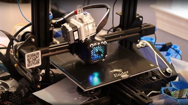
Taking a stock Ender 3 v2, [Nathan] first installs a dual Z axis kit, doubling up the Z axis screw and associated stepper motors. Likely this was needed to compensate for the additional weight of subsequent mods. Since the stock Ender mainboard has only one Z axis port, the less obvious solution was to just install a second mainboard! By leveraging the immense hackability of the Klipper printer firmware/software stack,he was able to get this weird configuration to work.
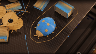
Next the main part of the build; the Phaetus Tai Chi dual hot end installation. For some reason, initially, it was decided to combine the stock bowden injector/extruder with a direct drive second unit, which we guess keeps the reciprocating weight down a bit and does let you directly compare bowden and direct drive print results on the same machine. Anyway, the first dual material prints came out pretty good after a few (quickly glossed over) fails, and did work well enough that dual-nylon printing could now be an option. After switching the build to a dual direct-drive setup, [Nathan] found it easier to get the machine to switch filaments more reliably, which makes sense when you think about the impact of all that extra filament in the bowden tube.
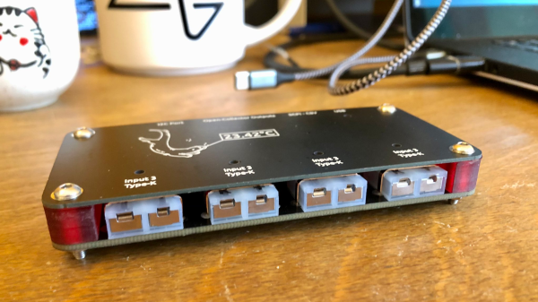
[Nathan] clearly has been burned (haven’t we all?) possibly literally, by the curious habit of some Chinese suppliers, of randomly assigning power supply polarity to red/black wire pairs. The solution, somewhat belt-and-braces, was to simply make up custom power cables with an embedded rectifier. Well, we guess that’s one less thing to worry about, but do look away when those PSU hacks are being shown!
Multi-material or multi-color FDM printer options are plenty, here’s a cool way of using a servo to swing a pair of hotends to the same point, and we also saw a while back, a way of using a sprung-loaded rocker to flip the unused hotend up out the way when not needed.
Continue reading “Doubled Up 3D Printer Upgrade Doubles The Fun”

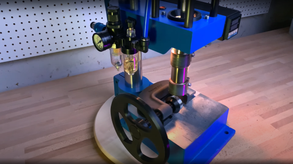
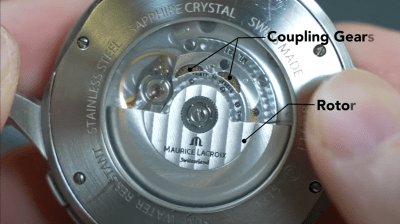 the centre of which has a one-way clutch, which transmits the torque onwards to the output gear. The input side of the clutch also drives an identical unit, which picks up rotations in the opposite direct, and also drives the same larger output gear. So simple, and watching this super-sized device in operation really gives you an appreciation of how elegant such mechanisms are. Could it be useful in other applications? How about converting wind power to mechanically pump water in remote locations? Let us know your thoughts in the comments down below!