[Advanced Tinkering] needed a source of fresh ozone for some future chemistry related projects, and since buying an off-the-shelf unit would be, well, just plain boring, it was obvious what to do (Video, embedded below).
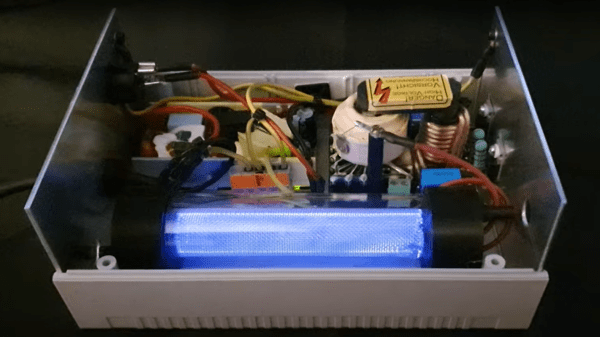
The concept of the corona-discharge ozone generator is pretty straightforward — a high-voltage AC potential is presented over a large surface area, such that any O2 in the vicinity has the chance to get a decent dose of electrons ripping it apart and enabling the formation of the desired O3.
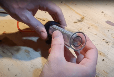
The construction is quite simple, just a pair of cylindrical metal wire mesh electrodes, separated by a glass tube, with a second glass tube surrounding the whole assembly. The use of high voltage AC allows the discharge to form by capacitive coupling across the central tube, giving a very simple construction. A pair of 3D-printed PLA end caps complete the reaction vessel, although it is noted in the video that the PLA is not terribly resistant to the corrosive effects of ozone, and time will tell whether these go the whole mileage.
Feed oxygen from an external generator is pumped into one end cap, at the bottom, with ozone-enriched gas passing out the other end, at the top, giving the gas a more complex path through the assembly and maximizing the contact with discharge. It will be interesting to see what the produced ozone will be used for in these future projects.
We’ve not seen a vast number of ozone hacks, but we’re no strangers to high voltage applications, like this interesting hand disinfection device, and this simple hack that generates a six-figure voltage with little more than some glasses of water, well not much more anyway.

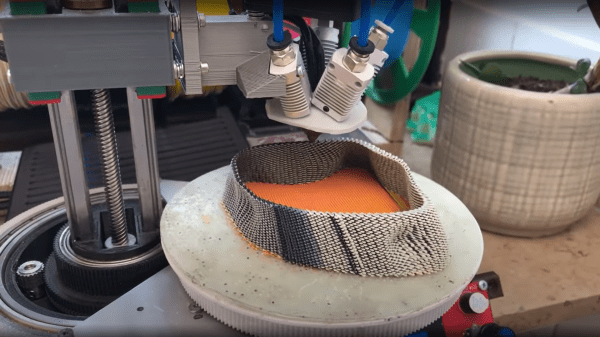
 trick is to use the same weight maps and simply map colours to blender text blocks which are injected into the gcode at export time. These gcode blocks can be used swap tool heads or extruders, enabling blending of multiple filament colours or types in the same object.
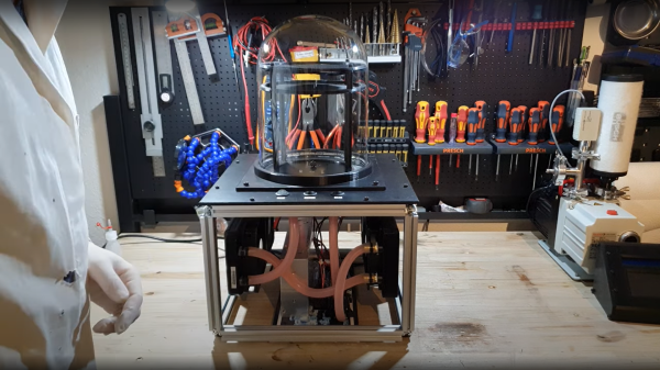
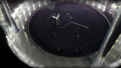 heat pump, so you need to dump the hot-side heat elsewhere. The method [Advanced Tinkering] chose here was to use a pair of off-the-shelf water cooling blocks, mounted into a 3D printed plate. The hot side dumps into a pair of fan-cooled radiators. Four double-layer Peltier modules are wired in parallel to a 60A power supply, which seems like a lot, but Peltier modules are hungry little things. A reasonable amount of power is needed to drive the cooling fans and water pump. The vapor source is a simple pad of liquid alcohol at the top of the stack, just above a metal screen which is held at a high voltage. The vertical electric field allows visualization of the charge of emitted particles, which will curve up or down depending on their polarity.