USB Meets Core Memory In A Vintage ‘Scope

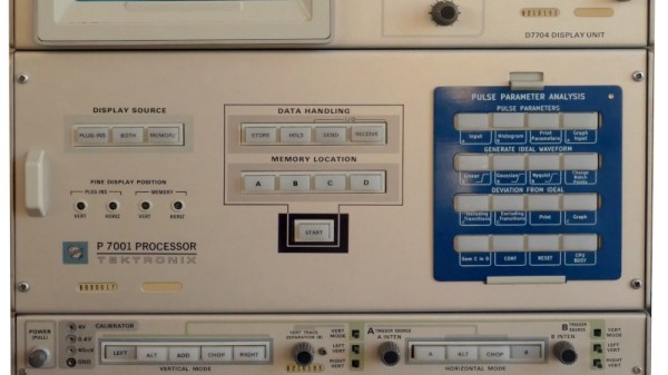
It’s normal today for even relatively modest instruments to have some form of computer control capability over Ethernet or USB. But five decades ago this was by no means a given, and when Tektronix shipped their P7001 digitiser module for their high-end oscilloscopes in 1971, they were initially designed to interface with a minicomputer. Not everybody has a PDP/11 lying around in 2023, but [Holger Lübben] wasn’t fazed by this. He set about creating a USB interface for this ancient piece of test equipment.

At its heart is a Teensy 4.1 which does the job of interfacing with the Tektronix 16-bit bus through a level shifting transceiver. The software for the Teensy comes with some demos, but sadly not the Tek BASIC of the original. We’re particularly impressed with the care to make the card frame for the module resemble as closely as possible an original Tektronix product.

We’re guessing very few of you will have this ancient test module on your bench, but the depth into which he goes over its internal design and programming makes this very much worth a read. If you fancy more vintage Tek goodness, take a look at this current probe.

Op-Amp Challenge: Compare Op-Amps, By Listening To Them

In the world of audiophilia there are arguments that rage over the relative merits of particular components. Sometimes this can reach silly levels as in the high-end ALPS pot we once saw chosen as a volume control whose only task was to be a DC voltage divider feeding a pin on a DSP, but there are moments where such comparisons might have a bit of merit. To allow the comparison of different op-amps in a headphone amplifier, [Stephan Martin] has created a stereo amplifier board complete with sockets to take single or dual op-amp chips.

The circuit is based upon a design from the 1990s which as far as we can see is a pretty conventional non-inverting amplifier. It has an on-board op-amp to create a virtual ground, and three sockets for either two single or one dual op-amp to create a stereo headphone amplifier.

So the burning question is this: will you notice a difference? We’re guessing that assuming the op-amps under test are to a sufficient specification with a high enough impedance input and enough output current capability, the differences might be somewhat imperceptible without an audio analyser or the hearing of a ten-year-old child.

Need more of an audio fix? Try our Know Audio series.


Op-Amp Challenge: A Low Noise Amplifier For Those Truly Low Noise Measurements

When something is described as “Low Noise”, it is by the nature of the language a relative phrase. The higest quality magnetic tape is low noise compared to its cheaper sibling for example, but still has noise many would consider unacceptable. In instrumentation however, “Low Noise” has to really mean just that, with a range of specialist techniques to produce circuitry with a truly low noise level for the most demanding of signal applications. As an example [Floydfish] has created a low noise instrumentation amplifier that should serve as a learning exercise for anyone interested in pushing low noise circuitry to the limit.

Anyone who can dredge the hazy recesses of their mind for barely-remembered electronics lectures will know that the overall noise figure of a system is dictated by that of its first component. Thus perhaps the most interesting part of the schematic is at the input, where a row of low-noise op-amps are presented in parallel. We have to admit having to look this one up, to find that it’s a technique whereby the signal outputs of each chip are the same and thus sum, while the noise output of each is different and thus the summed noise output is proportionally lower. This stage is then followed by a buffer and a set of filters for different output frequency ranges.

Our op-amp competition of which this is a part is certainly delivering the goods when it comes to the amny techniques with which these versatile parts can be used. Few of us may need to make such a low noise amplifier, but at least now we’ve learned how.

Op-Amp Challenge: Light Up Breadboard Shows Us The Signals

Most Hackaday readers will no doubt at some point used a solderless breadboard for prototyping. They do the job, but sometimes their layout can be inflexible and keeping track of signals can be a pain. There’s a neat idea from [rasmusviil0] which might go some way to making the humble breadboard easier to use, it’s a breadboard in which each line is coupled via an op-amp buffer to an LED. In this way it can be seen at a glance some indication of the DC voltage present.

It’s an idea reminiscent of those simple logic probes which were popular years ago, but its implementation is not entirely easy. Each circuit is simple enough, but to replicate it across all the lines in a breadboard makes for a huge amount of quad op-amp chips stuffed onto one piece of stripboard as well as a veritable forest of wires beneath the board.

The effect is of a breadboard crossed with a set of blinkenlights, and we could see that for simple digital circuits it could have some utility if not so much for higher frequency or analogue signals. Certainly it’s an experiment worth doing, and indeed it’s not the first tricked out breadboard we’ve seen.

Op-Amp Challenge: Get More From A Single Wire With An Analogue Adder

It’s been a running battle in some quarters for years, whether analog sensor processing is better than digital. Proponents of digital are sometimes driven by lack of familiarity with analog circuitry, while analog die-hards point to delays and software crashes in microcontrollers. We’d probably toe the line that a mixture of the two skills is best, but [paul] has gone full-on for the analog side with his position and limit sensor for a remote telescope. The ‘scope had only one control wire carrying a digital signal, so how was he to get extra information down it? The solution was to overlay a DC voltage, and use a summing network composed of a series of op-amps to encode position and limit data as voltage.

In operation, the circuit is a straightforward DC summing amplifier of the type that op-amps were designed for and at which they excel. We’re not so sure it needs the high-precision resistors and the choice of op-amps seems the wrong way round with the AD8532’s high current output being better suited to driving the line than straightforward summing, but we can see it does the job. If you’re after a demonstration of a DC summing amplifier using an op-amp, here’s your project. Meanwhile if you’re curious about an op-amp inside the black box, take a look at one of the simplest integrated circuit op-amps ever made.

Op-Amp Challenge: Reliable Peak Power Measurement

As part of our Op-Amp Challenge we’re seeing a wide diversity of entries showcasing the seemingly endless capabilities of these extremely versatile parts. Another one comes from [Joseph Thomas], who when faced with the need to measure the properties of an automotive spark plug, came up with a precision peak detector to hold on to the energy level used when firing it.

It starts with an op-amp buffer feeding a diode and capacitor. The capacitor is charged through the diode and holds the level, which can be read through another op-amp. Finally there’s an opto-isolated transistor to discharge the capacitor before a fresh reading is taken.

It’s a simple enough circuit but a very effective one. The op-amps used are bit old-school FET devices, but aside from the high impedance input their performance is hardly critical. Yet another op-amp circuit to hold in reserve should you ever need to perform this task.

Op Amp Challenge: An Ultra-Cheap PH Sensor Amplifier

It’s rare in 2023 for an instrument to be entirely analog, instead it’s more normal for a front-end to feed the analog-to-digital converter (ADC) in a microcontroller. Typically the front-end will do the job of transforming whatever the output range of the sensor is, and present it to the microcontroller in whatever range it accepts. [David] had exactly this problem with a pH sensor, and rather than buy an expensive module to do the job he designed his own.

The sensor in question produces a relatively tiny voltage of -0.414 to +0.414 volts, and requires a very high input impedance. A FET input op-amp is selected, with the ground of the sensor shifted upwards into the positive range by a voltage divider. This then feeds a second op-amp that amplifies the resulting DC voltage for the microcontroller input.

This circuit is an especially simple op-amp application, and is a typical one for a sensor interface where a DC voltage needs to be brought into range of a microcontroller. If you’re not used to op-amp circuits then take a look, this type of analogue circuit is not difficult and might just save your butt some time.

Want to know more about simple op-amp circuits? Have we got the video for you!