Turn An Ender 3 Into A Belt 3D Printer Of Your Very Own

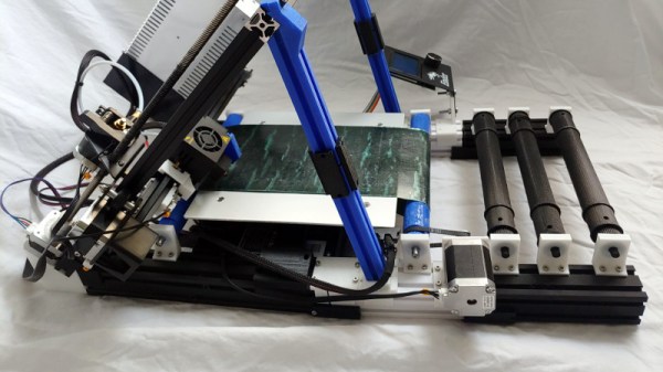
Infinite-bed 3D printers have long been an object of desire in our community, but it has taken a long time for the promise to catch up with the reality in terms of relatively affordable models that live up to expectations. They’re still a little expensive compared to their fixed-bed cousins though, so if you hanker for a Creality CR30 but only have the cash for an Ender 3, [Michael Sgroi] may have the project for you. He’s created the EnderLoop, a set of parts to perform the conversion from a stock Ender 3 to a fully-functional belt printer.

It takes the Ender 3 gantry and tilts it sideways on a pair of 3D printed supports, and replaces the stock Y azis with a belt on rollers driven by a larger motor through a timing belt drive. He has a variety of suggestions for sourcing a belt, and in his case he’s chosen one from PowerBelt3D. As well as the GitHub repository already linked, it can also be found on Thingiverse.

It’s clear that hacking apart a reliable printer in this way is not for the faint-hearted, and that a cautious hacker might prefer to wait a while for a cheaper off-the-shelf model. But we can see that the reliability of the Ender 3 will mean that its parts are still of decent quality in the new configuration, and that it looks as though the base printer can be reassembled should a belt-based build be a failure. Infinite bed printers will inevitably have a major presence in our community, and it is designs such as this one which will lead the way as they evolve into reliable machines.

Taking A Capacitor Microphone To The Next Level

There was a time when a microphone for most people was a cheap plastic affair that probably came for free with their sound card, but in the age of pandemic video streaming no desktop is complete without a chunky model that looks for all the world as though it escaped from a studio. Few people make their own microphones, so the work of [DJJules] in building very high quality condenser microphones is a particularly fascinating read.

A condenser microphone is a capacitor in which one plate is formed by a conductive diaphragm. A bias voltage is supplied to the diaphragm via a resistor, and since the charge on the plate remains constant as its capacitance changes with the sound vibrations, the voltage on the capacitor changes accordingly. This is picked up by a high impedance buffer and from there fed to a normal microphone input. This Instructable uses a commercial condenser microphone capsule, and takes the reader through generating the bias voltage for it before describing the op-amp buffer circuit.

The most interesting part comes at the end, as we’re shown how the sensitivity pattern of a dual-microphone array can be tuned to be omnidirectional, cardoid, or figure-of-eight. This is probably the norm among audio engineers, but we rarely see this sort of insight in our community. We may never build a microphone of our own, but it’s fascinating to see this one from the ground up in the video below the break.

If you’re confused about the difference between a condenser microphone and the more common electret condenser microphone, we have published a guide to that topic. Continue reading “Taking A Capacitor Microphone To The Next Level”

Mastering The Tricky Job Of Soldering SMA Connectors

There’s a satisfaction in watching someone else at work, particularly when they are demonstrating a solution to a soldering problem you have encountered in the past. SMA panel sockets have a particularly tiny solder bucket on their reverse, and since they often need to be soldered onto brass rod as part of microwave antenna construction they present a soldering challenge. [Andrew McNeil] is here to help, with a foolproof method of achieving a joint that is both electrically and mechanically sound.

The best connections to a solder bucket come when the wire connected to it nestles within its circular center. If this doesn’t happen and a blob of solder merely encapsulates both wire and bucket, the mechanical strength of the solder blob alone is not usually sufficient. The brass rod is wider than the bucket, so he takes us through carefully grinding it down to the right diameter for the bucket so it sits in place and can have the solder sweated into the gap. The result is very quick and simple, but has that essential satisfaction we mentioned earlier. It’s a small hack, but if you’ve ever soldered to a too-small RF connector you’ll understand. For more fun and games with RF connectors, take a look at our overview.

Continue reading “Mastering The Tricky Job Of Soldering SMA Connectors”

How Tiny Can A Microcontroller Dev Board Be!

With innumerable microcontroller boards on the market it’s sure that there will be one for every conceivable application or user. Among them are some seriously tiny ones, but this wasn’t enough for [Alun Morris]. Wanting to see how small he could make an ATtiny board without a custom PCB, he took a SOIC-8 version of the popular minimalist processor and mated it to a 6mm by 8mm piece of 0.05″ prototyping board to create a device that is dwarfed by its connectors.

It’s an extremely simple circuit and hardly something that hasn’t been done before, but the value here is in the tricky soldering to make it rather than its novelty. The ATtiny402 and three passive SMD components are fitted on the smallest possible sliver of prototyping board to contain them, and the female headers and set of programming pins contribute far more to the volume of the device than the board itself. He also tried a side-on design with two smaller slivers of board before settling on the more conventional layout. The demonstration of the system in action seen in the video below the break is a magnetic flux detector, dwarfed by the 40-pin DIP Z80 it is sitting on.

A lot of boards claim to be tiny, but few are this small. This ESP32 is a more usual contender.

Continue reading “How Tiny Can A Microcontroller Dev Board Be!”

Volumetric 3D Television Is Here!

Volumetric 3D displays that allow the viewing of full 3D images without special glasses are not unknown in our community, usually taking the form of either a 3D LED matrix or a spinning rotor either with an image projected onto it or holding an LED array. They are impressive projects, but they are often limited in what they can display. Pretty patterns and simple 3D models are all very well, but they are hardly 3D television. Thus we’re quite impressed with [Evlmnkey]’s bachelor’s degree project, which combines motion capture and a volumetric display for a genuine volumetric 3D closed-circuit television system.

Finding the details takes a bit of dredging through the Reddit thread, but the display is an off-the-shelf Adafruit single-sided LED matrix driven by an ESP32, all mounted on a motor with a pair of slip rings for power. Data is fed to the ESP via WiFi, with the PC responsible for grabbing the image sending it as uncompressed frames. There’s little detail on the 3D capture, but since he mentions a Kinect library we suspect that may be the source.

This is perhaps not the highest resolution TV you’ll ever have seen, indeed we’d liken it to the flickering 30 lines of 1930s mechanical TV, but it’s still a functioning volumetric 3D live CCTV system. If you’re interested by 3D displays, you might like to see our examination of the subject.

Thanks [nandkeypull] for the tip.

How Did The Nintendo Virtual Boy Work?

What do you know about the Nintendo Virtual Boy? Everybody knows that it was the console giant’s mid-90s foray into 3D graphics and VR, and that it was a commercial flop. Sickness and headache-inducing graphics are probably first to mind, and that’s it. But since most of us will never have handled one in real life, all we have on this legendary console is this Received Opinion. What was it Really like? [Rodrigo Copetti] has put up a detailed technical examination, and it reveals a machine well ahead of its time in more than just the market it was trying to create.

The first surprise is that this machine eschews the expected LCD screens that were the norm on handheld consoles of the day, instead using a persistence-of-vision display with a single vertical bar of LEDs facing a vibrating mirror through a lens system. He goes into significant detail on how this system worked, and in doing so gives us a new respect for the console.

The meat of this article lies though in a detailed look at the console’s architecture. The NEC V810 CPU was significantly more powerful than those in other portable consoles of the day, and we get a peek of how it and the custom silicon handled the graphics. The GPU had dual framebuffers for each display to ensure each frame could be delivered smoothly while the next one was being created.

Everything that can be said about the Virtual Boy in the marketplace has been done to death, leading to the received opinion we mentioned at the start of the article. This write-up provides new information on one of Nintendo’s rarer machines and casts it in an entirely new light.

There have been understandably few Virtual Boy projects that have made it to these pages. One that has, was a VGA interface for the console.

Via Hacker News.

The Raspberry Pi Pico Can’t Run Linux. But It Can Run Fuzix.

The great divide in terms of single board computers lies between those that can run some form of Linux-based distribution, and those that can not. For example the Raspberry Pi Zero is a Linux board, while the Raspberry Pi Pico’s RP2040 processor lacks the required hardware to run everybody’s favourite UNIX-like operating system. That’s not to say the new board from Cambridge can’t run any UNIX-like operating system though, as [David Given] shows us with his Fuzix port.

Fuzix is a UNIX-like operating system for less capable processors, more in the spirit of those original UNIXes than of a modern Linux-based distribution. It’s the work of the respected former Linux kernel developer and maintainer [Alan Cox], and consists of a kernel, a C compiler, and a set of core UNIX-like applications.

The RP2040 port maybe needs a little more work to be considered stable. For now, the multitasking support isn’t quite there and NAND flash support is broken, but it does have SD card support for a proper UNIX filesystem and the full set of core tools. Perhaps most interestingly, it only occupies a single core of the dual-core chip, leaving the possibility of the other core and those PIOs to be used for other purposes.

Fuzix has made the occasional appearance here over the years, but perhaps not as often as it should. If you’d like to learn a little more about the genesis of UNIX, we took a look in 2019.

Header: Michiel Henzler (CC BY-SA 4.0).