It’s a Holy Grail among hackerspaces, the possession of a pick-and-place machine. These robotic helpers for placing surface-mount components on PCBs are something of a gateway to electronic production, but they can carry a fearsome cost. Happily for the cash-strapped would-be electronic manufacturer, it is possible to build a pick-and-place for yourself. [Mcuoneclipse] has demonstrated this with a rather impressive build that works with the freely available OpenPnP software.
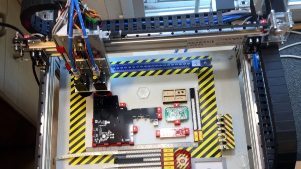
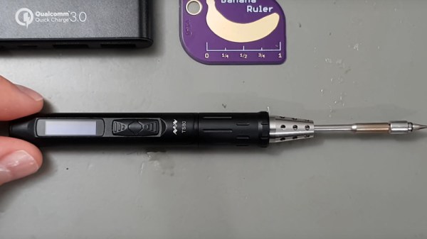
Superficially it shares much with what you might expect from a small CNC mill, in that it has a frame made from extruded aluminium that carries rails that trace an X and a Y axis supporting a tool head. But instead of a blade it has a box made from laser-cut ply that contains a camera and a vacuum pick-up tool that can collect a component from the tapes and deposit it in the correct point on the board. At the machine’s heart is a Smoothieboard, and the work is done by an assortment of solenoid valves and actuators. A huge amount of attention to detail has been paid to this build, with a holder for all the interchangeable nozzles for different component sizes, laser-cut mountings for all the motorised components, and automatic feeders for the SMD tapes all being carefully designed and built. Several iterations of the design are presented, in particular around the head itself which has passed through more than one form to remove as much vibration as possible. But don’t take it from us, have a look at the video we’ve pasted in below the break.
This isn’t the first pick-and-place machine we’ve brought you here at Hackaday. If you already have a 3D printer, would you consider this upgrade?

 Lexicographic research comes from huge corpora, databases of tens or hundreds of millions of words of written English, from which they can extract the subtlest of language trends to see where a word is going. These can be interesting and engrossing tools for anyone, not just linguists, so we’d urge you to