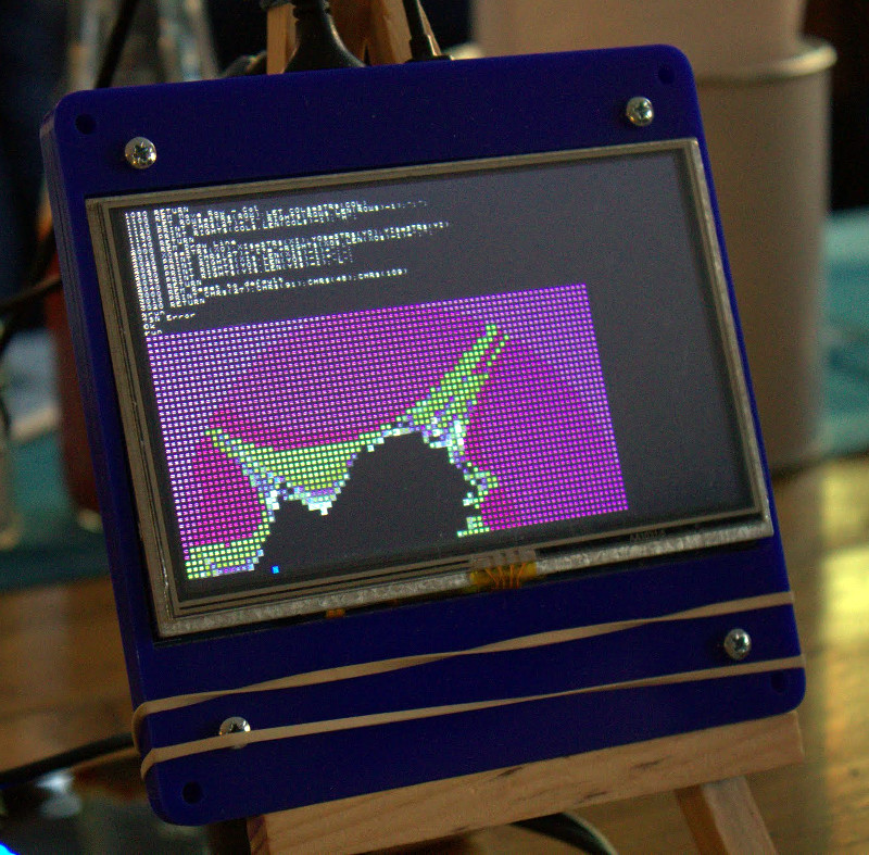
How many grown-up hardware hackers whiled away their youth playing Tetris or Mario on their Game Boy? Fond memories for many, but unless you are lucky your Game Boy will probably be long gone. Not for [Gautier Hattenberger] though, he had an unexpected find at his parents’ house; his Game Boy Classic, unloved and forgotten for all those years. Fortunately for us his first thought was whether he could use it as a controller for a drone, and better still he’s shared his work for all of us to see.
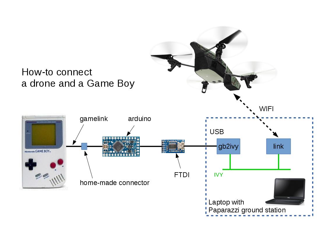
How to connect a drone and a Game Boy
Back in the day a would-be Game Boy hacker would have been deterred by Nintendo’s legal defences against game piracy, but with the benefit of a couple of decades the handheld console’s hardware is now an open book. Unfortunately for [Gautier], he seems to be the first to use one as a flight controller, so he had to plough his own furrow. His Game Boy Game Link serial port feeds an Arduino/FTDI combination that converts Game Link to USB, which is then sent to his laptop on which a small piece of software converts them to commands for the drone through the Paparazzi UAV framework.
All his code is in a GitHub repository, and he’s posted a video of his work which you can see below the break. For a child of the early ’90s, the mere thought that their handheld console could do this would have been mindblowing!
If you watch Pokémon Go enthusiasts, you may have noticed something of a community spirit among gamers congregating at busy in-game locations. [Spencer Kern] wanted to encourage this, so produced what he describes as a water cooler for Pokémon Go players, a Pokémon-styled charging station with multiple USB ports.
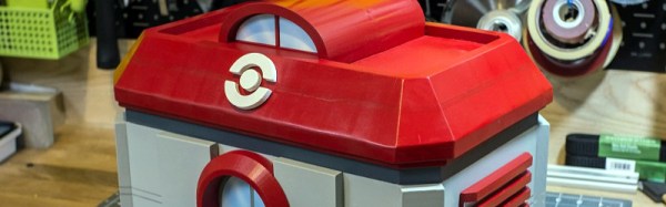
His build centres on a Yeti 400 solar power pack and a large multi-port USB hub, for which he has built a detailed wooden housing in the style of a Pokémon Center from the earlier Nintendo games. The idea is that gamers will congregate and plug in their phones to charge, thus bringing together a real-world social aspect to the game. We can see the attraction to gamers, however we suspect most Hackaday readers would join us in not trusting a strange USB socket and using only a USB cable not equipped with data conductors.
Still, the housing has seen some careful design and attention to detail in its construction. He started with a 3D CAD model from which he created a set of 2D templates to print on paper and from which to cut the wood. As many of his dimensions as possible were taken from common wood stock to save machining time, and the structure was assembled using wood glue before being sanded and filled. Finally, the intricate parts such as the Pokémon logo were 3D printed, and spray painted. The result is a pretty good real-world replica of the Pokémon Center that you’d recognise if you were a player of the original games, and he reports it was a hit with gamers in his local park.
If you have ever spent a while delving into the bare metal of talking to the I/O pins on a contemporary microprocessor or microcontroller you will know that it is not always an exercise for the faint-hearted. A host of different functions can be multiplexed behind a physical pin, and once you are looking at the hardware through the cloak of an operating system your careful timing can be derailed in an instant. For these reasons most of us will take advantage of other people’s work and use the abstraction provided by a library or a virtual filesystem path.
If you have ever been curious enough to peer under the hood of your board’s I/O then you may find [Ken Shirriff]’s latest blog post in which he explores the software stack behind the pins on a BeagleBone Black to be of interest. Though its specifics are those of one device, the points it makes have relevance to many other similar boards.
He first takes a look at the simplest way to access a Beagle Bone’s I/O lines, through virtual filesystem paths. He then explains why relying so heavily on the operating system in this way causes significant timing issues, and goes on to explore the physical registers that lie behind the pins. He then discusses the multiplexing of different pin functions before explaining the role of the Linux device tree in keeping operating system in touch with hardware.
For some Hackaday readers this will all be old news, but it’s safe to say that many users of boards like the BeagleBone Black will never have taken a look beyond the safely abstracted ways to use the I/O pins. This piece should therefore provide an interesting education to the chip-hardware novice, and should probably still contain a few nuggets for more advanced users.
If you had made it this far in your journey from project to kit, you would now have a box of electronic components, a pile of printed instructions, and a box of plastic bags, thin card boxes, or whatever other retail packaging you have chosen for your kit. You are ready to start stuffing kits.
It’s All In The Presentation
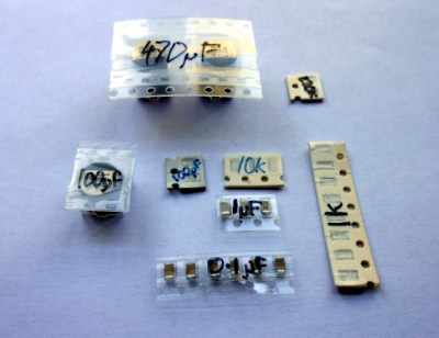
Label all your hard-to-identify components, your customers will appreciate it.
Your priorities when stuffing a kit are to ensure that your customer receives all the components they should, they can easily identify each component, and that the whole kit is attractively presented such that it invites them to buy or build it when they first see it. This starts before you have packed any components, you must carefully prepare each component into units of the required number and label them if they are otherwise not easy to identify. Pre-cut any components supplied on tape, and write the part number or value on the tape if it is not easily readable. You may even have to package up some difficult-to-identify components in individual labeled bags if they can not have their values written on them, though this incurs an extra expense of little bags and stickers. Some manufacturers will insist on using black tape on which an indelible pen doesn’t show up!
Take care cutting tapes of components, it is sometimes easy to damage their pins. Always cut the tape from the bottom rather than the side with the peelable film, and if necessary carefully bend the tape slightly to open up the gap between components for your scissors.
If you start by deciding how many kits you want to stuff in a sitting, list all the kit components and prepare that number of each of them in the way we’ve described. Then take the required number of packages or bags, and work through each component on the list, stuffing all the bags with one component before starting again moving onto the next. In time you will have a pile of stuffed kits ready to receive their instructions and labeling.
The next step will be to fold your instruction leaflet and pack it in the kit. Take a moment to consider how it can be most attractively presented. For example with a kit packaged in a click-seal plastic bag it makes sense to fold the leaflet such that the colour photo of a completed kit is visible from the front. And when you place it in the bag make sure that the PCB is visible top-outwards in front of it. A customer looking at your kit wants to immediately see what they are likely to create with it.
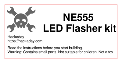
You can now seal the bag or box, the kit is packed. It only remains to give it a label that has all the pertinent information and is attractive to the customer. You will probably want to put your logo or web address on the label as well as any small print required, alongside the most important feature — the kit description. We’ve put a warning about small parts and curious children, you may also want to put any reglatory or compliance information here. For example in Europe you might have a CE mark and a WEEE logo. Once you have your design sorted you can run it up in your favourite label designing software – we used gLabels – and print as many as you like on sheets of sticky labels. We strongly suggest buying good quality branded labels, the extra money is well worth it when you consider that they will have much more reliable glue, and the extra cost per individual kit will be marginal. Pick a label size which fills a decent space and is easy to read on your packaging without being too big, we used 70mm x 37mm laser labels of which 24 can be had on a single sheet.
Your First Finished Product
If Hackaday made electronic kits, they might look a little like this.
It’s an exciting moment when you apply a label to your first fully packed kit and see for the first time what your customers will see: a finished product. You aren’t quite done though, because there is still the small matter of quality control. Take a kit or two from your batch at random, and count all their contents off against your list of what they should contain. This should help you ensure you are packing the kits correctly. Finally, give a completed kit to a friend who has never seen it before, and tell them to build it as a final piece of quality control. They are simulating your customer in every way, if they have no problems then neither should anyone who buys the kit.
Once you’ve built your batch of kits, you will now have the stock you will send out to your customers. Imagine yourself as a customer, if you order a kit you will expect it to arrive in pristine condition. You should therefore now take care of this stock of kits to ensure that it does not come to any harm, its packaging is as crisp and new when you send it out as when you packed it, and it has not attracted any dust while in storage. We would suggest having a separate plastic box for the stock of each kit in your range, and protecting the kits from dust with a lid, or by storing them inside a larger plastic bag.
As we’ve worked through this series of articles, we’ve tried to give you a flavour of the process of bringing an electronic kit from a personal project to the masses. We’ve looked at learning about the market for your kit, we’ve discussed turning a project into a product before writing the best instructions possible and now stuffing your first kits ready for sale. In the next article in the series we’ll talk about how you might sell your products, the different choices open to you for online shops, marketplaces, and crowdfunding.
We’ve been all over the UK this month, our most recent Hackaday gathering just two nights past. With much hardware and hacker show and tell (recounted below) I wanted to make sure nobody missed the chance to join in as we’ll be in Bletchley on Saturday and in Cambridge on Wednesday. Whether you need more convincing to walk out the door and join in the fun, or just want to the see the excellent hardware so far displayed, keep reading to share in the fun from Wednesday night.
London pubs have an unfavourable image among provincial folk, one of being strange neon-lit places populated by vast crowds of very loud people in suits drinking cheap wine at expensive prices. The truth is though that the capital’s pubs are as diverse as those anywhere else in the country, from shabby quiet backstreet boozers with their aged customers nursing pints of Fullers to achingly hipster faux-Victorian gin-palaces in which young men sporting preposterous beards they’ll regret in five years time drink microbrewery ales you won’t have heard of served in glass tankards. On a hot August evening the patrons spill out onto the pavement and provide a handy reference to the would-be drinker as to the nature of the establishment.
This warm-evening exodus served our community well night before last, for when a group of Hackaday readers and Tindie sellers converged upon a pub in Fitzrovia there was enough room to reach the bar and though it was hardly quiet we could at least discuss the things we’d brought along. My colleague [Jasmine] had organised the event and was on hand with a pile of stickers and other swag.
A select group of hackers and makers made the journey. Some of them, such as my friend [David], I had encountered frequently online but never met in person so it was good to put a face to a name, while others I knew only by the reputation they had garnered through the projects they’d put on Hackaday.io or Tindie. I will undoubtedly fail to mention a few names in this quick round-up of a few of the projects, so before I start I would like to thank everyone for coming along and making it such a good evening.
[Jasmine] as seen by [Mike]’s LED screen.
Electric Stuff from Mike’s Workshop
Most visible because of an extensive range of very bright LED projects was [Mike], of [Mike’s Electric Stuff] fame. His PCB density was impressive, though he did admit to having a pick-and-place machine. Especially useful for those large LED matrices. Of note was a pentagonal LED screen with integrated camera, originally part of an LED screen polyhedron. This board offered a rare glimpse of a Raspberry Pi Compute Module in the wild.
Scope Probe Sans Pound Sink
Opposite me for most of the evening was [Leonerd], with his oscilloscope current probe adapter. This board as you might expect contains a very low value shunt resistor and an amplifier, allowing the accurate measurement of low current transients without laying down the GDP of a small country to buy one from a high-end test equipment manufacturer. I was party to a very interesting conversation between him and [Mike] on the subject of instrumentation amplifiers, something of personal interest from my experience with RF test equipment.
The RC2014 in mid-render
A Wild Z80 Appeared
Also present was [Spencer] with his RC2014 Z80-based computer. He’d brought along the fully tricked-out version with keyboard and screen, and had it running a fractal graphic generator written in BASIC. It’s a project that touches a spot in the heart of people of a certain age, if your first computer came from Sir Clive Sinclair then maybe you’ll understand.
The value of the evening was not solely in the kits and projects on display though. Whenever you get a group from our wider community together in a convivial environment the creative discourse flows in unexpected direction, knowledge is shared, and new ideas are formed. Part of the global Hackaday and Tindie community got to know each other yesterday evening, and from that will come fresh projects. They may not necessarily change the world, but everything has to start somewhere.
This event was one of a short series following our successful bring-a-hack at EMF Camp. We were very pleased to see the projects people brought along, they comprehensively eclipsed the little radio board that was my offering. The run of UK events isn’t over, we have ones coming up at Bletchley and Cambridge, and as always keep an eye on the Hackaday.io events page for global events within our community.
We use touch screens all the time these days, and though we all know they support multiple touch events it is easy for us to take them for granted and forget that they are a rather accomplished sensor array in their own right.
[Optismon] has long held an interest in capacitive touch screen sensors, and has recently turned his attention to the official Raspberry Pi 7-inch touchscreen display. He set out to read its raw capacitance values, and ended up with a fully functional 2D capacitive imaging device able to sense hidden nails and woodwork in his drywall.
Reading the capacitance values is not a job for the faint-hearted though. There is an I2C bus which is handled by the Pi GPU rather than the processor, and to read it in software would require a change to the Pi’s infamous Broadcom binary blob. His solution which he agrees is non-optimal was to take another of the Pi’s I2C lines that he could talk to and connect it in parallel with the display line. As a result he can catch the readings from the screen’s sensors and with a bit of scripting make a 2D display on the screen. The outlines of hands and objects on his desk can clearly be seen when he places them on the screen, and when he runs the device over his wall it shows the position of the studding and nails behind the drywall.
It’s probable that most Hackaday readers are aware of their own computer security even if they are not specialists. You’ll have some idea of which ports your machines expose to the world, what services they run, and you’ll know of a heap of possible attack vectors even if you may not know about every last one.
So as part of that awareness, it’s likely you’ll be wary of strange USB devices. If someone drops a Flash drive in the parking lot the chances of one of you blithely plugging it into your laptop is not high at all. USB ports are trusted by your computer and its operating system, and to have access to one is to be given the keys to the kingdom.
Our subject today is a DEF CON talk courtesy of [Dominic White] and [Rogan Dawes] entitled “Universal Serial aBUSe“, and it details a USB attack in which they create an innocuous USB stick that emulates a keyboard and mouse which is shared across a WiFi network via a VNC server. This gives an attacker (who can gain momentary physical access to a USB port to install the device) a way into the machine that completely bypasses all network and other security measures.
Their hardware features an AVR and an ESP8266, the former for USB and HID work and the latter to do the heavy lifting and provide WiFi. They started with a Cactus Micro Rev2, but graduated to their own compatible board to make the device more suitable to pose as a USB stick. Both hardware and software files can be found on their GitHub repository, with the software being a fork of esp-link. They go into significant detail of their development and debugging process, and their write-up should be an interesting read for anyone.
Below the break you can find a video description of the attack. It’s not a shock to know that USB ports have such little defense, but it is a sobering moment to realize how far attacks like this one have come into the realm of what is possible.

 Still, the housing has seen some careful design and attention to detail in its construction. He started with a 3D CAD model from which he created a set of 2D templates to print on paper and from which to cut the wood. As many of his dimensions as possible were taken from common wood stock to save machining time, and the structure was assembled using wood glue before being sanded and filled. Finally, the intricate parts such as the Pokémon logo were 3D printed, and spray painted. The result is a pretty good real-world replica of the Pokémon Center that you’d recognise if you were a player of the original games, and he reports it was a hit with gamers in his local park.
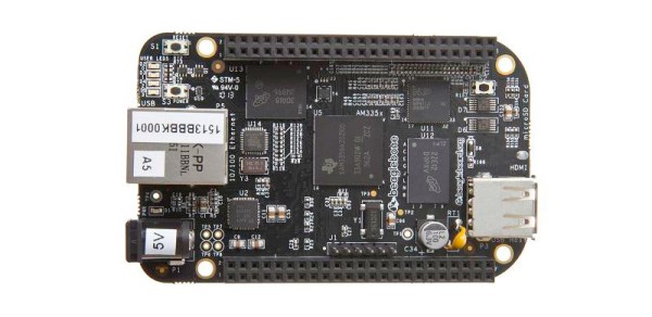

 You can now seal the bag or box, the kit is packed. It only remains to give it a label that has all the pertinent information and is attractive to the customer. You will probably want to put your logo or web address on the label as well as any small print required, alongside the most important feature — the kit description. We’ve put a warning about small parts and curious children, you may also want to put any reglatory or compliance information here. For example in Europe you might have a CE mark and a WEEE logo. Once you have your design sorted you can run it up in your favourite label designing software – we used
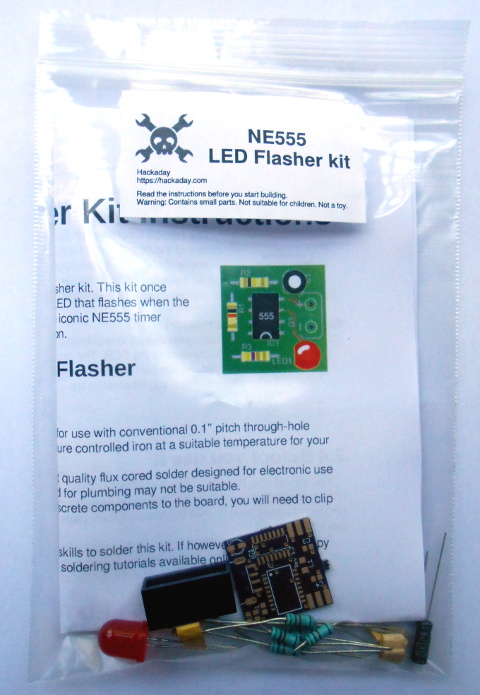

![[Jasmine] as seen by [Mike]'s LED screen.](https://hackaday.com/wp-content/uploads/2016/08/jasmine-on-screen.jpg)