In the early days of broadcast television, national spectrum regulators struggled to reconcile the relatively huge bandwidth required by the new medium with the limited radio spectrum that could be allocated for it. In the USA during the years immediately following World War Two there was only a 12-channel VHF allocation, which due to the constraints of avoiding interference between adjacent stations led to an insufficient number of possible transmitter sites to cover the entire country. This led the FCC in 1949 to impose a freeze on issuing licences for new transmitters, and left a significant number of American cities unable to catch their I Love Lucy or The Roy Rogers Show episodes.
The solution sought by the FCC was found by releasing a large block of UHF frequencies between 470 and 890 MHz from their wartime military allocation, and thus creating the new channels 14 to 83. An experimental UHF pilot station was set up in Bridgeport, Connecticut in 1949, and by 1952 the FCC was ready to release the freeze on new licence applications. The first American UHF station to go on air was thus KPTV in Portland, Oregon, on September 18th of that year.
UHF TV was a very new technology in 1952, and was close to the edge of what could be achieved through early 1950s consumer electronics. Though the 525-line TV standard and thus the main part of the sets were the same as their VHF counterparts, the tuner designs of the time could not deliver the performance you might expect from more recent sets. Their noise levels, sensitivity, and image rejection characteristics meant that UHF TV reception did not live up to some of its promise, and thus a fierce battle erupted between manufacturers all keen to demonstrate the inferiority of their competitors’ products over the new medium.
The video below the break delivers a fascinating insight into this world of claim and counter-claim in 1950s consumer electronics, as Zenith, one of the major players, fires salvos into the fray to demonstrate the superiority of their products over competing models or UHF converters for VHF sets. It’s very much from the view of one manufacturer and don’t blame us if it engenders in the viewer a curious desire to run out and buy a 1950s Zenith TV set, but it’s nonetheless worth watching.
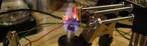
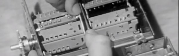
A key plank of the Zenith argument concerns their turret tuner. The turret tuner was a channel selection device that switched the set’s RF front end between banks of coils and other components each preset to a particular TV channel. Zenith’s design had a unique selling point that it could be fitted with banks of components for UHF as well as VHF channels thus removing the need for a separate UHF tuner, and furthermore this system was compatible with older Zenith sets so existing owners had no need to upgrade. Particularly of its time in the video in light of today’s electronics is the section demonstrating the clear advantages of Zenith’s germanium mixer diode over its silicon equivalent. Undeniably true in that narrow application using the components of the day, but not something you hear often.