Pillaging The Wealth Of Information In A Datasheet

It’s a fair assumption that the majority of Hackaday readers will be used to working with electronic components, they are the life blood of so many of the projects featured here. In a lot of cases those projects will feature very common components, those which have become commoditized through appearing across an enormous breadth of applications. We become familiar with those components through repeated use, and we build on that familiarity when we create our own circuits using them.

All manufacturers of electronic components will publish a datasheet for those components. A document containing all the pertinent information for a designer, including numerical parameters, graphs showing their characteristics, physical and thermal parameters, and some application information where needed. Back in the day they would be published as big thick books containing for example the sheets for all the components of a particular type from a manufacturer, but now they are available very conveniently online in PDF format from manufacturer or wholesaler websites.

A 2N3904 in a TO92 through-hole package

Datasheets are a mine of information on the components they describe, but sometimes they can be rather impenetrable. There is a lot of information to be presented, indeed when the device in question is a highly integrated component such as a DSP or microprocessor the datasheet can resemble a medium-sized book. We’re sure that a lot of our readers will be completely at home in the pages of a datasheet, but equally it’s a concern that a section of the Hackaday audience will not be so familiar with them and will not receive their full benefit. Thus we’re going to examine and explain a datasheet in detail, and hopefully shed some light on what it contains.

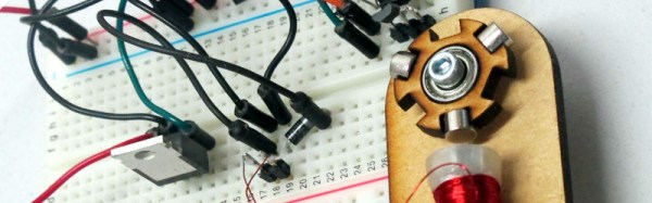
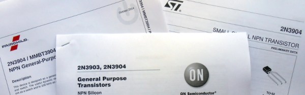
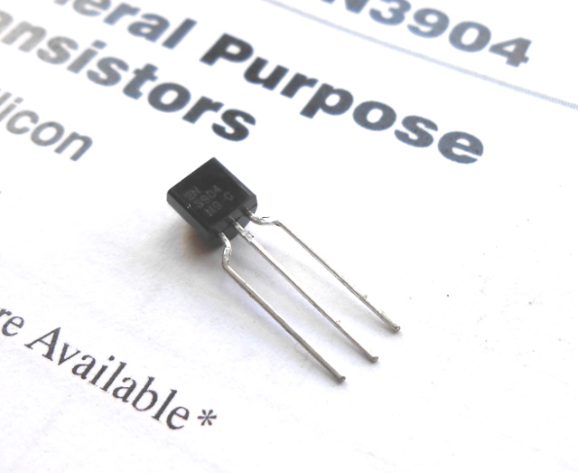
The device whose datasheet we’ve chosen to put under the microscope is a transistor. The most basic building block of active semiconductor circuits, and the particular one we’ve chosen is a ubiquitous NPN signal transistor, the 2N3904. It’s been around for a very long time, having been introduced by Motorola in the 1960s, and has become the go-to device for a myriad circuits. You can buy 2N3904s made by a variety of manufacturers all of whom publish their own data sheets, but for the purposes of this article we’ll be using the PDF 2N3904 data sheet from ON Semiconductor, the spun-off former Motorola semiconductor division. You might find it worth your while opening this document in another window  or printing it out for reference alongside the rest of this article.

Let’s take a look at all the knowledge enshrined in this datasheet, and the engineering eye you sometimes need to assign meaning to those numbers, diagrams, and formulas.

Continue reading “Pillaging The Wealth Of Information In A Datasheet”

Retrotechtacular: MONIAC

There is an argument to be made that whichever hue of political buffoons ends up in Number 10 Downing Street, the White House, the Élysée Palace, or wherever the President, Prime Minister or despot lives in your country, eventually they will send the economy down the drain.

Fortunately, there is a machine for that. MONIAC is an analogue computer with water as its medium, designed to simulate a national economy for students. Invented in 1949 by the New Zealand economist [WIlliam Phillips], it is a large wooden board with a series of tanks interconnected by pipes and valves. Different sections of the economy are represented by the water tanks, and the pipes and valves model the flow of money between them. Spending is downhill gravitational water flow, while taxation is represented by a pump which returns money to the treasury at the top. It was designed to represent the British economy in the late 1940s as [Philips] was a student at the London School of Economics when he created it. Using the machine allowed students and economists for the first time to simulate the effects of real economic decisions in government, in real time.

So if you have a MONIAC, you can learn all about spectacularly mismanaging the economy, and then in a real sense flush the economy down the drain afterwards. The video below shows Cambridge University’s restored MONIAC in operation, and should explain the device’s workings in detail.
Continue reading “Retrotechtacular: MONIAC”

Workshops For Timid Solderers

As a hackspace member, it’s easy to fall into the belief that your own everyday skills are universal. Soldering for example. You’ve handled an iron since you were a youngster, the solder bends to your will as a matter of course, and since you see your fellow makers doing the same thing you might imagine that it’s a universal hackspace skill. Everyone can do it, can’t they?

Of course, they can’t. If you weren’t lucky enough to have a parent who tolerated your occasional propensity for acquiring burns on your fingers then you probably won’t have that innate experience with an iron. This extends to people you might expect to have those skills, indeed as an electronic engineering student a couple of decades ago your scribe was surprised to find that the ability to solder was her hotly tradeable skill, amazingly even a lot of EE students couldn’t solder.

So the ability to solder is not as universal as we might expect, and your hackspace will attract plenty of people for whom it is an as-yet-unknown art. What do you do about it? If you are Vancouver Hackspace, you run a workshop whose participants are introduced to soldering through building a simple AM radio. The kit itself is not too special, it looks like one of the Elenco educational kits, but it is what the workshop represents that is important. A hackspace lives or dies by how it shares its skills, and Vancouver’s workshop is a fantastic piece of community engagement. We’d like to see more spaces doing this kind of thing.

So, perhaps it’s time to put our money where our mouth is. How difficult would it be to run a hackspace soldering workshop for the uninitiated? Assuming your space is used to the mechanics of running events, the challenge is to find for each participant a soldering iron, some solder, and a radio or other kit without breaking the bank. An ideal budget from where this is being written in the UK would be £20 (about $29), into which a Chinese kit from AliBaba or similar and a cheap iron kit could be fitted. Some work to decipher the Chinese instructions with the help of an overseas student member and to write an English manual, and we’d be ready to go. If this comes together we’ll report back on whether the non-solderers of our hackspace successfully learned the craft.

We recently featured a similar educational initiative, a course at Swansea Hackspace teaching robotics through an Arduino robot. We would like to encourage this kind of thing, what is your hackspace doing in this line?

Fail Of The Week: Don’t Tie Those Serial Lines High

Fail Of The Week is a long-running series here at Hackaday. Over the years we’ve been treated to a succession of entertaining, edifying, and sometimes downright sad cock-ups from many corners of the technological and maker world.

You might think that we Hackaday writers merely document the Fails of others, laughing at others’ misfortunes like that annoying kid at school. But no, we’re just as prone to failure as anyone else, and it is only fair that we eat our own dog food and tell the world about our ignominious disasters when they happen.

And so we come to my week. I had a test process to automate for my contract customer. A few outputs to drive some relays, a few inputs from buttons and microswitches. Reach for an Arduino Uno and a prototyping shield, divide the 14 digital I/O lines on the right into 7 outputs and 7 inputs. Route 7 to 13 into a ULN2003 to drive my relays, tie 0 to 6 high with a SIL resistor pack so I can trigger them with switches to ground. Job done, and indeed this is substantially the hardware the test rig ended up using.

So off to the Arduino IDE to write my sketch. No rocket science involved, a fairly simple set of inputs, outputs, and timers. Upload it to the Arduino, and the LED on pin 13 flashes as expected. Go for a well-deserved lunch as a successful and competent engineer who can whip up a test rig in no time.

Back at the bench refreshed by the finest British pub grub, I started up the PC, plugged the shield into the Arduino, and applied the power. My sketch worked. But wait! There’s a slight bug! Back to the IDE, change a line or two and upload the sketch.

And here comes my fail. The sketch wouldn’t upload, the IDE reported a COM port error. “Damn’ Windows 10 handling of USB serial ports”, I thought, as I’m not a habitual Windows user on my own machines. Then followed something I’ve not done for quite a while; diving into the Windows control panel to chase the problem. Because it had to be a Windows problem, right?

arduino-serial-pins
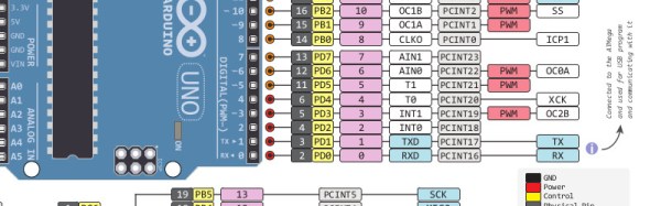
The seasoned Arduinisti among you probably spotted my fail four paragraphs ago. We all know that pins 0 and 1 on an Arduino are shared with the serial port, but who gives it a second thought? I guess I’d always had the good fortune to drive those pins from lines which didn’t enforce a logic state, and had never ended up tying them high. Hold them to a logic 1, and the Arduino can’t do its serial thing so sketches stay firmly in the IDE.

I could have popped the shield off every time I wanted to upload a new sketch, but since in the event I didn’t need all those inputs I just lifted the links tying those pins high and shifted the other inputs up the line. And went home that evening a slightly less competent engineer whose ability to whip up a test rig in no time was a bit tarnished. Ho hum, at least the revised sketch worked and the test rig did its job exactly as it should.

So that’s my Fail Of The Week. What’s yours?

Header image: pighixxx.com, CC-BY-ND via MarkusJenkins


2013-09-05-Hackaday-Fail-tips-tileFail of the Week is a Hackaday column which celebrates failure as a learning tool. Help keep the fun rolling by writing about your own failures and sending us a link to the story — or sending in links to fail write ups you find in your Internet travels.

From Trash To TV

In days gone by, when TVs had CRTs and still came in wooden cabinets, a dead TV in a dumpster was a common sight. Consumer grade electronic devices of the 1960s and ’70s were not entirely reliable, and the inside of a domestic TV set was not the place for them to be put under least stress. If you were electronic-savvy you could either harvest these sets as a source of free components, or with relative ease fix them for a free TV set.

With today’s LCDs, integrated electronics, and electronic waste regulations, the days of free electronics in every dumpster are largely behind us. Modern TVs are more reliable, and when they reach end-of-life we’re less likely to see them.

[Sidsingh] happened to find an LCD TV in a dumpster, and being curious as to whether he could fix it or salvage some components, cracked it open to take a look.

He found that somebody had already been into the set and that some components on the PSU and backlight boards showed evidence of magic smoke escaping, having been desoldered by the previous repairer. The signal board was intact though, a generic Chinese model based around a Mediatek MTK8227 SoC. Information was scarce on these boards, but some patient research yielded a schematic for a similar set.

Once he knew more about the circuit, he was able to identify the power lines and discovered that the 1.8v line to the SoC was faulty. This he traced to a switching regulator for which there was no equivalent in his junkbox, so he substituted a linear regulator to obtain the required voltage. The CFL backlight was then removed and replaced with LED strips, and as if by magic he had a working TV set.

This might seem a relatively mundane achievement on the scale of some of the projects we feature on these pages, but it is an important one. In these days of throwaway items it is still not impossible to repair dead electronic devices, indeed as [Sidsingh] found the power supply is most likely to be the culprit. If you score a dead LCD TV then don’t be afraid to crack it open yourself, you may be able to fix it.

As you might imagine, many repairs have made it onto Hackaday over the years. Of relevance to this one is this LCD that inexplicably worked when exposed to light, an LED backlight conversion, and this capacitor swap to return an LCD monitor to health.

A Simple And Educational Brushless Motor

Sometimes there is no substitute for a real working model to tinker with when it comes to understanding how something works. Take a brushless motor for example. You may know how they work in principle, but what factors affect their operation and how do those factors interact? Inspired by some recent Hackaday posts on brushless motors, [Matt Venn] has built a simple breadboard motor designed for the curious to investigate these devices.

The rotor and motor bodies are laser-cut ply, and the rotor is designed to support multiple magnet configurations. There is only one solenoid, the position of which relative to the magnets on the rotor can be adjusted. The whole assembly is mounted on the edge of a breadboard, and can be rotated relative to the breadboard to vary the phase angle at which the drive circuit’s Hall-effect sensor is activated by the magnet. The drive circuit in turn can have its gain and time constants adjusted to study their effects on the motor’s running.

[Matt] has made all the design files available in his GitHub repository, and has recorded a comprehensive description of the motor’s operation in the YouTube video below the break. Continue reading “A Simple And Educational Brushless Motor”

A 3D-Printed Engagement Ring

[Hans Peter] had reached the moment of popping the question. Going down on one knee and proposing to his girlfriend, the full romantic works.

He’s a brave man, [Hans]. For instead of heading for the jeweller’s and laying down his savings on something with a diamond the size of a quail’s egg he decided that his ring should contain something very much of him. So he decided to 3D print a ring and embed a slowly pulsing LED in it. He does mention that this ring is a temporary solution, so perhaps his soon-to-be-Mrs will receive something sparkly and expensive in due course.

To fit his LED and flasher in such a small space he used a PIC10F320 microcontroller that comes in a SOT-23-6 package. This was chosen because it has a handy PWM output to pulse the LED rather than flash it. This he assembled dead-bug style with an 0603 LED, and a couple of hearing aid batteries to power the unit. He has some concerns about how long the hearing aid batteries will power the device, so as he wrote he had better hurry and get on his knees. (He informs us in his tip email that she said yes.)

Surprisingly we’ve covered quite a few engagement ring builds over the years. Closest to this one is an LED ring powered by an induction coil, but we’ve also featured machined titanium rings and some rather nice cast rings.