Electronic Driver Replaces Master Clock

In these days of cheap microprocessors and easy access to accurate timing through NTP or from the likes of MSF, WWVB, or DCF77, it’s no problem to ensure that any number of clocks keep the same time. In a simpler age though they didn’t have these tools at their disposal, so when a large organisation wished to ensure that all its parts ran on the same time they used an electromechanical solution. A master clock of as high a quality as the clockmakers of the day could build was fitted with a microswitch. The switch would send pulses to slave clocks which had a solenoid where a traditional clock has a pendulum. Thus every clock in the system lost or gained time at the same rate.

[Edo Lelic] has a rather nice Iskra slave clock, but unfortunately not the master that once drove it. Undeterred by this setback, he’s created an electronic driver board that generates the required 100mS pulses. His weapon of choice was a PIC microcontroller and an H-bridge driver to deliver their required voltage and polarity. The clock was designed to accept 100V pulses, but since it has an internal series resistor he determined that the solenoid was happy with a mere 24V. Source code is available, downloadable at the bottom of the linked article.

These clocks are an unseen piece of technology that is disappearing without our noticing. If you find one – or even better if you find a master clock – you’ll find it to be a very high quality timepiece indeed. A master clock would be well worth snapping up. At least now you won’t have to look too far for a driver for it.

We haven’t seen too many projects like this here at Hackaday. Save for a rather nice digital master clock build, it’s uncharted territory. Almost justification for a Retrotechtacular piece, perhaps.

Thanks [Muris Pučić] for the tip.
Classic Amplifier Reborn With Modern Transistors

Someone brought a dead Marantz amplifier to [Lansing]’s attention, a rather nice model from the 1980s with one channel entirely dead and the other very quiet. His account of its repair is straightforward, but provides some insights should you find yourself with a similar item on your bench.

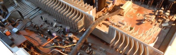
Opening up the box, he was presented with 35 years of accumulated dust. It’s the annoying side of cracking open classic kit, we all have our dusty horror stories. His first task was routine: to replace all the unit’s capacitors. The mains voltage in France has gone up by 10 volts from 220V to 230V as part of EU harmonization in the years since the amp was built, so he used capacitors with an appropriately higher rating to compensate. We might have waited until the rest of the amp was proven fixed before splashing the cash on caps, but maybe we’re more thrifty.

The quiet channel fix turned out to be from a muting circuit designed to keep the amp quiet during the turn-on phase and suppress that annoying “thump”. A dead transistor replaced, and all was well. The dead channel though had a whole slew of dead transistors in it, which turned the problem from one of repair to one of transistor equivalence. Quite a few of the 1980s parts were no longer available, so modern replacements had to be found.

It is tempting to think of particularly all small-signal transistors as functionally equivalent. You will get away with this in logic and switching circuits in which the device is either On or Off and never in between, but in an audio amplifier like the Marantz things are not so simple. A lot of effort will have been made by the designers to calculate resistances for the current passing through them to deliver the right DC bias points without sending the circuit into wild oscillation. An important part of that calculation comes from the current gain of the transistors involved. [Lansing] had to carefully select his transistors for equivalence, though it some cases he had to do a bit of creative lead-bending to fit a different pin-out.

So, all dead transistors replaced with appropriate equivalents, and the amp was reborn. Success, and very much worth the effort!

We’ve covered a lot of amplifiers here in the past. Some were dead, like this little amp with blown capacitors or this smokin’ subwoofer. Others are more esoteric, like this ion wind 1KV tube creation.

Taming A Variac With A Thermistor

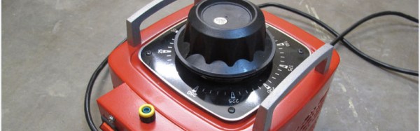
The folks at TOG, Dublin Hackerspace, have a large variac. A variac is a useful device for testing some fault conditions with AC mains powered equipment, it allows an operator to dial in any AC output voltage between zero, and in the case of TOG’s variac, 250V.

Their problem was with such a magnificent device capable of handling nearly 3KW, it presented an inductive load with a huge inrush current at power-on that would always take out the circuit breakers. Breakers come with different surge current handling capabilities, evidently their building is fitted with the domestic rather than the industrial variants.

Their solution was a simple one, they fitted an NTC surge limiter in series with the variac input. This is a thermistor whose resistance falls with temperature. Thus on start-up it presented an extra 12 ohm load which was enough to keep the breaker happy, but soon dropped to a resistance which left the variac with enough juice.

This is a simple fix to a problem that has faced more than one hackerspace whose imperfect lodgings are wired to domestic-grade spec. In a way it ties in neatly with our recent feature on mains safety; making the transformer no longer a pain to use means that it is more likely to be used when it is needed.

Via: TOG, Dublin Hackerspace.

Chibiterm Is A Tiny Low-Cost VGA Terminal

A common sight in the days before cheap PCs conquered the world was the dumb terminal. A keyboard and a monitor with a serial port on the back that was usually hooked up to a minicomputer or even a mainframe, these were simple devices. Anything that came into the serial port was rendered on the screen, anything typed on the keyboard was sent out through the serial port. They didn’t need to contain a microprocessor. If you are old enough, you may remember electronics magazines of the 1970s and early 1980s publishing terminal designs based entirely on 74 series logic.

The serial terminal might seem like a redundant historical footnote when viewed from 2016, but they can still find a use among those working with systems such as small embedded microcontrollers that only possess a serial port. To address this application, Hackaday.io user [K.C.Lee] has created a low-cost terminal module for a VGA monitor and a PS/2 keyboard based around an inexpensive STM32F030F4 processor.

Continue reading “Chibiterm Is A Tiny Low-Cost VGA Terminal”

Digitize Your Graphs With WebPlotDigitizer

Have you ever had to write a bit of code to interpret a non-linear analog reading as picked up by an ADC? When all you have to work with for your transfer function is a graph in a semiconductor datasheet that was probably written thirty years ago and prints out the size of a postage stamp, that’s a rather annoying task. Wouldn’t it be nice if you had access to the numbers behind the graph!

You can’t knock on the office door of the engineer who created it back in the ’80s, he’s probably  in retirement and playing golf or growing prize petunias by now. But you can digitize the graph to get yourself a lot closer to the action, and to help you in your quest there’s a handy online tool.

2N3904-current-gain
2N3904 current gain

WebPlotDigitizer is not new, it’s been around for quite a few years now. But it’s still worth talking about, because it’s one of those tools to keep in reserve. If you’ve ever needed it, you’ll know what we mean.

So how does it work? Load an image with a graph in it, select some points on the X and Y axis, roughly trace the curve with a marker tool, and set it in motion. Let’s give it a go. We’re going to try digitizing the current gain plot from the 2N3904 datasheet (PDF) that we examined a few days ago.

data-points
Data points!

So, open the WebPlotDigitizer app, load the graph image captured from the sheet as a JPEG. It asks what type of graph you’ve loaded, in this case a 2D X-Y plot. It asks you to identify four known points on the axes and supply their values. You also tell it if the axes are logarithmic at this point. Select “Automatic mode” on the right hand side, then click “Pen” and mark the graph trace, then select the colour of the trace. Click the “Run” button, and your data points appear. Hit the “View data” button, and there you have it. A few rogue points to remove perhaps, but it does a pretty good job.

If WebPlotDigitizer has engaged your interest, you’ll be pleased to know that it’s open-source, and you can find all its code on GitHub. There is also a handy video tutorial which you can see below the break. Continue reading “Digitize Your Graphs With WebPlotDigitizer”

Looking Mains Voltage In The Eye And Surviving

It is often a surprise to see how other people react to mains electricity when they encounter it in a piece of equipment. As engineers who have dealt with it both personally and professionally for many years it is easy to forget that not everyone has had that experience. On one hand we wince at those who dive in with no fear of the consequences, on the other we are constantly surprised at the number of people who treat any item with more than a few volts in it as though it was contaminated with radioactive anthrax and are scared to even think about opening it up.

We recently had a chat among the Hackaday writers about how we could approach this subject. The easy way out is to be all Elf-and-Safety and join the radioactive anthrax crowd. But the conclusion we came to was that this site is a resource for hackers and makers. Some of you are going to lift the lid on boxes containing significant voltages no matter what, so we thought we’d help you do it safely rather than just listen for the distant screams.

So here follows the first in a series on how to approach electronic devices containing high voltages, and live to tell the tale. By “high voltages” we mean anything up to mains voltages, and those directly derived from them such as the few hundred volts rectified DC you’ll find in a switch-mode PSU. For multi-kilovolt EHT you’ll have to wait for another article, because that is an entire subject in itself. We’ll mention these higher voltages in passing, but their detail is best left for a Hackaday colleague with more pertinent experience.

Continue reading “Looking Mains Voltage In The Eye And Surviving”

An Affordable Ultrasonic Soldering Iron

One of the most interesting facets of our community of hackers and makers comes from its never-ending capacity to experiment and to deliver new technologies and techniques. Ample demonstration of this came this morning, in the form of [Hunter Scott]’s Hackaday.io project to create an ultrasonic soldering iron. This is a soldering technique in which the iron is subjected to ultrasonic vibrations which cavitate the surface of the materials to be soldered and remove any oxides which would impede the adhesion of the solder. In this way normally unsolderable materials such as stainless steel, aluminium, ceramic, or glass can be soldered without the need for flux or other specialist chemicals. Ultrasonic soldering has been an expensive business, and [Hunter]’s project aims to change that.

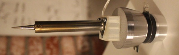
This iron takes the element and tip from a conventional mains-powered soldering iron and mounts it on the transducer from an ultrasonic cleaner. The transducer must be given an appropriate load which in the case of the cleaner is furnished by a water bath, or it will overheat and burn out. [Hunter]’s load is just a soldering iron element, so to prevent transducer meltdown he keeps the element powered continuously but the transducer on a momentary-action switch to ensure it only runs for the short time he’s soldering. The project is not quite finished so he’s yet to prove whether this approach will save his transducer, but we feel it’s an interesting enough idea to make it definitely worth following.

This is the first ultrasonic soldering project we’ve featured here at Hackaday. We have however had an ultrasonic plastic welder before, and an ultrasonic vapour polisher for 3D prints. It would be good to think this project could spark a raft of others that improve and refine DIY ultrasonic soldering designs.