A Keypad Joypad For Your Retro Gaming

[TK] is a retro computer enthusiast who’s had some difficulty locating a joystick for his trusty Amiga 500. New ‘sticks are expensive, and battered survivors from the 80s go for more than they should.

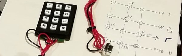
Happily these old controllers were simple devices, having only five control lines for the four directions and a fire button which were active low. [TK] therefore cast around the available components and decided to craft his own controller from a numerical keypad.
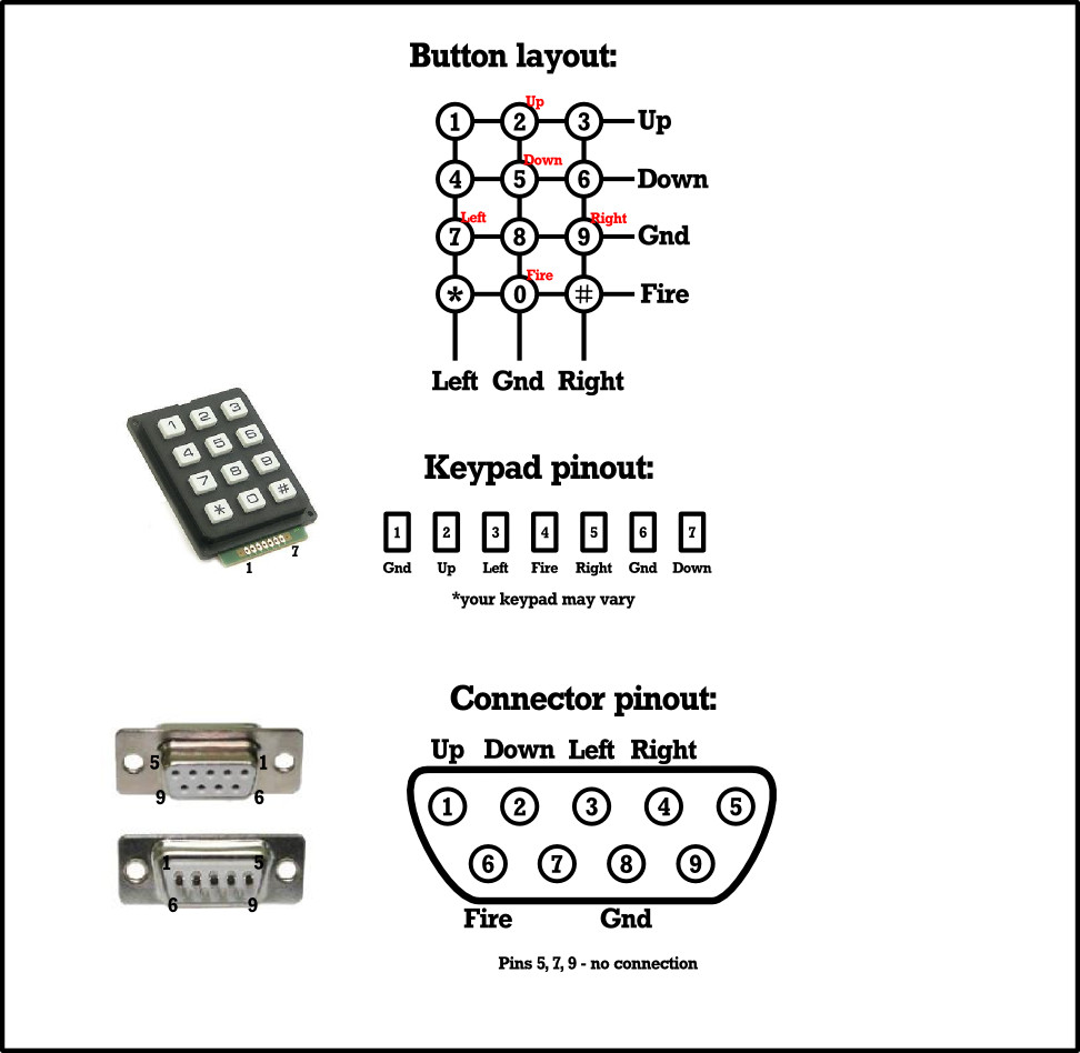
Numerical joypad schematic

Numerical keypads may be ubiquitous, but they’re not the perfect choice for a joypad. Instead of individual switches, they are wired as a matrix. [TK]’s controller works within that constraint without butchering the keypad PCB, though his layout has the left and right buttons below the up and down buttons. Looking at the schematic we wonder whether the 4-5-6 and 7-8-9 rows could be transposed , though joypad layout is probably a matter of personal choice.

Making the controller was a simple case of wiring the pad to a 9-pin D socket in the correct order, and plugging it into the Commodore. He reports that it’s comfortable to use and better than some of the lower-quality joysticks that were on the market back in the day. Veterans of Amiga gaming will understand that sentiment, there were some truly shocking offerings to be had at the time.

Quite a few home-made game controllers have made it onto these pages over the years. There is this one using tactile switches and a ballpoint pen, and a stick made from the idler wheel from a surplus VCR, but the ultimate crown of junkbox joysticks should go to this joystick made from clothes pins. If we take one thing away from all this home-made controller ingenuity, it is that what really matters is not the hardware but the gameplay.

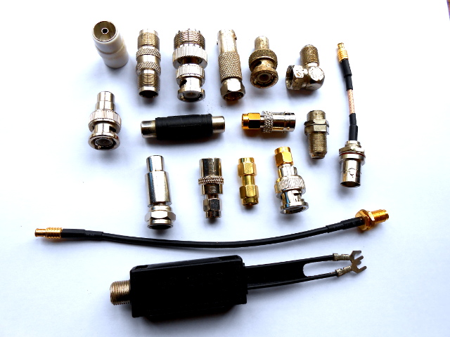
Co-Exist With Your Coax: Choose The Right Connector For The Job

Just a selection from the author's unholy assortment of adaptors.
Just a selection from the author’s unholy assortment of adaptors.

If you do any work with analogue signals at frequencies above the most basic audio, it’s probable that somewhere you’ll have a box of coax adaptors. You’ll need them, because the chances are your bench will feature instruments, devices, and modules with a bewildering variety of connectors. In making all these disparate devices talk to each other you probably have a guilty past: at some time you will have created an unholy monster of a coax interface by tying several adaptors together to achieve your desired combination of input and output connector. Don’t worry, your secret is safe with me.

Continue reading “Co-Exist With Your Coax: Choose The Right Connector For The Job” →

Intel Ups The Dev Board Ante With The Quark D2000

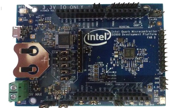
Intel have a developer board that is new to the market, based on their Quark (formerly “Mint Valley”) D2000 low-power x86 microcontroller. This is a micropower 32-bit processor running at 32MHz, and with 32kB of Flash and 8kB of RAM. It’s roughly equivalent to a Pentium-class processor without the x87 FPU, and it has the usual impressive array of built-in microcontroller peripherals and I/O choices.

The board has an Arduino-compatible shield footprint, an FTDI chip for USB connectivity, a compass, acceleration, and temperature sensor chip, and a coin cell holder with micropower switching regulator. Intel provide their own System Studio For Microcontrollers dev environment, based around the familiar Eclipse IDE.

Best of all is the price, under $15 from an assortment of the usual large electronics wholesalers.

This board joins a throng of others in the low-cost microcontroller development board space, each of which will have attributes that its manufacturers will hope make it stand out. Facing such competition the Intel board will have to be something rather special to achieve that aim, so why should it excite your interest? We would point to the low price, the x86 code if that is your flavour of choice, and the relatively tiny power consumption.

Stepping back from the dev board for a moment, consider this processor as an illustration of technological progress in semiconductor fabrication. Over twenty years ago this chip’s Pentium ancestor ran on 5 volts and got so hot you could fry an egg on it, here is a Pentium that can run on a few milliwatts from a coin cell. Fortunately you won’t be running Windows 95 on it though.

We’re sure we’ll see plenty of projects here in the future using the Quark. Intel’s previous effort in this space, the Edison, has made several appearances. We’ve covered its launch in 2014, looked at someone running Doom on it, and examined its use with audio effects.

Thanks [Nolan M] for the tip.

A Ridiculous Way To Light An LED: Candle-power

If you have ever entertained yourself by reading comprehensive electronic-theory textbooks you’ll have seen references to technologies that sound really interesting but which you will rarely hold in your hand. They may be dead-ends that have been superseded by more recent innovations, or they may be technologies that have found uses but in other fields from those in which they originally showed promise. What if you could take these crazy parts and actually build something?

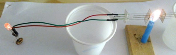
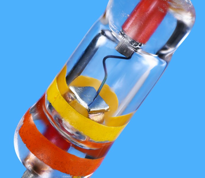
[Fedetft] has an interesting project that combines two of those intriguing textbook references, he’s created a thermopile that lights an LED through an inverter whose oscillator is a tunnel diode. Dig out the textbook.

If you’ve used a thermocouple thermometer or a semiconductor thermoelectric generator then you’ll have encountered the thermoelectric effect. Perhaps you’ve even operated a Peltier cooling element in this mode. When a circuit is made with two junctions between different types of conductor with a temperature difference between the two junctions, a current will flow in the circuit which is dependent on both the scale of the temperature difference and the properties of the conductors.

A thermopile is a collection of these thermoelectric junction circuits between metal conductors, arranged in series to increase the voltage. [Fedetft]’s thermopile uses chromel and alumel wires taken from a K-type thermocouple. He’s made six sets of junctions, and supported them with small pieces of mica sheet. Using the heat from a candle he found he could generate about 200mV with it, at about 3.7mW.

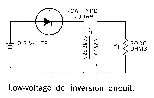
The RCA tunnel diode inverter circuit

Such a tiny source of electricity would be of little use to light an LED directly, so he needed to build an inverter. And that’s where the tunnel diode comes in. Tunnel diodes have a negative-resistance region that can be used to amplify and oscillate at extremely high frequencies in extremely simple circuits, yet they’re not exactly a device you’d encounter very often in 2016. [Fedetft] has a Russian tunnel diode, and he’s used it with a toroidal transformer in an inverter circuit he found in an RCA tunnel diode manual from 1963. It’s a two-component Joule Thief. The RCA manual is a good read in itself for those curious about tunnel diodes.

The resulting circuit produces a 15kHz oscillation with 4.5v peaks, and has just enough power to light an LED.

While it might seem pointless to barely light an LED from a brightly lit candle, the important part of [Fedetft]’s project is to gain some understanding of two of those technological backwaters from the textbooks. And we applaud that.

It’s the mark of a truly esoteric technology that it features rarely on Hackaday, and neither of these two disappoint. We’ve only mentioned tunnel diode in passing when looking at diodes in general, and we’ve tended to use “thermopile” in another sense to refer to thermal imaging cameras.

Retrotechtacular: Hallicrafters Goes To War

When the USA entered World War Two, they lacked a powerful mobile communications unit. To plug this gap they engaged Hallicrafters, prewar manufacturers of amateur radio transmitters and receivers, who adapted and ruggedized one of their existing products for the application.

The resulting transmitter was something of a success, with production running into many thousands of units. Hallicrafters were justifiably proud of it, so commissioned a short two-part film on its development which is the subject of this article.

The transmitter itself was a very high quality device for the era, but even with the film’s brief insight into operating back in the AM era the radio aspect is not what should capture your interest. Instead of the radio it is the in-depth tour of an electronics manufacturing plant in the war years that makes this film, from the development process of a military product from a civilian one through all the stages of production to the units finally being fitted to Chevrolet K-51 panel vans and shipped to the front. Chassis-based electronics requiring electric hoists to move from bench to bench are a world away from today’s surface-mount micro-circuitry.

So sit back and enjoy the film, both parts are below the break.

Continue reading “Retrotechtacular: Hallicrafters Goes To War” →

555 Plasma Speaker

The 555 can do anything. OK, that’s become a bit of a trope in our community, but there is quite a lot of truth behind it: this little timer chip is an astonishingly versatile component.

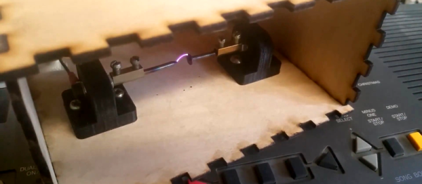
[Alexander Lang] has added another achievement to the 555’s repertoire, he’s used one in the creation of a plasma speaker. Working at Hackspace Manchester, he’s used the 555 as a pulse-width modulator that drives a flyback transformer through a MOSFET, which feeds a spark gap mounted in a lasercut enclosure. The results maybe aren’t yet hi-fi, but it works, and is very audible.

We’ve been following this project for a while, as he’s updated his progress through several iterations. From initial design idea through PCB and enclosure design, to a first working prototype and some audio refinements, and finally this latest post with the spark gap in its enclosure. He is still refining his speaker, so there is more to come

In the video below the break he demonstrates his pulse width modulator, and tests the device using a keyboard as an input.

Continue reading “555 Plasma Speaker” →

RF Biscuit Is A Versatile Filter Prototyping Board

As anyone who is a veteran of many RF projects will tell you, long component leads can be your undoing. Extra stray capacitances, inductances, and couplings can change the properties of your design to the point at which it becomes unfit for purpose, and something of a black art has evolved in the skill of reducing these effects.

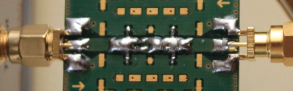
RF Biscuit is [Georg Ottinger]’s attempt to simplify some of the challenges facing the RF hacker. It’s a small PCB with a set of footprints that can be used to make a wide range of surface-mount filters, attenuators, dummy loads, and other RF networks with a minimum of stray effects. Provision has been made for a screening can, and the board uses edge-launched SMA connectors. So far he’s demonstrated it with a bandpass filter and a dummy load, but he suggests it should also be suitable for amplifiers using RF gain blocks.

Best of all, the board is open source hardware, and as well as his project blog he’s made the KiCad files available on GitHub for everyone.

It’s a tough challenge, to produce a universal board for multiple projects with very demanding layout requirements such as those you’d find in the RF field. We’re anxious to see whether the results back up the promise, and whether the idea catches on.

This appears to be the first RF network prototyping board we’ve featured here at Hackaday. We’ve featured crystal filters before, and dummy loads though, but nothing that brings them all together. What would you build on your RF Biscuit?