Touring Component Markets In Shenzhen

touring-component-markets-in-shenzhen

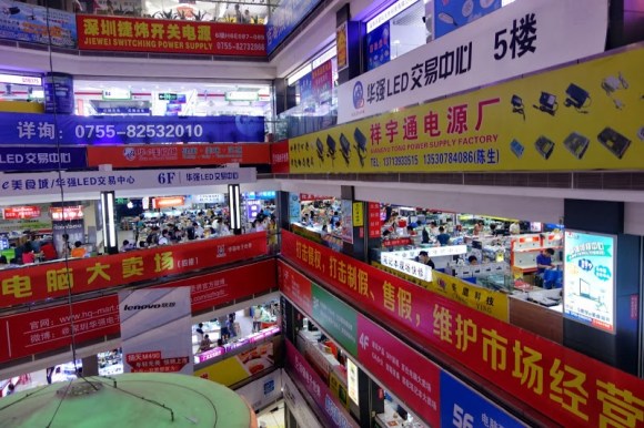
[Al] recently returned from a trip to China. While there he toured some of the component markets in Shenzhen, the electronics assembly epicenter of the world. While he doesn’t focus too closely on what is actually being sold there, we found his description of the markets themselves and other notable attractions around the area quite interesting.

Shenzhen is different from some of the other component wonderlands we’ve heard about ([Ian Lesnet’s] tour of Akihabara in Japan comes to mind). First of all it may be a bit more difficult to get there. US Citizens need a Visa to enter China, and must fly to Hong Kong and take a ferry to the mainland. [Al] reports that the traffic is horrendous and rush-hour can turn a ten mile ride that usually takes ninety minutes into a three hour tour… a three hour tour!

The side affect of the market being out of the way is that the prices aren’t as inflated as they may be in more geek-tourist-friendly locations. That being said it also sounds like the vendors are interested in selling you a few thousand units rather than a single component. Follow the link at the top for the market tour, a stop at Seeed Studios (who will apparently sell you a map of the best markets to visit), and the rest of the attractions that [Al] encountered.

Breadboard Tetris Is Wire Artwork

RGB-module-breadboard-tetris

Look closely at the colored pixels on this pair of 8×8 RGB LED modules and you’ll be able to pick out some of the familiar shapes of Tetris pieces. It’s impressive that [Jianan Li] built his own color Tetris including the theme music, but look at this breadboard! The layout of his circuit is as equally impressive as the code he wrote to get the game up and running. It takes a fair amount of planning to get a circuit of this complexity to fit in the space he used, right?

There are two microcontrollers at work, each running the Arduino bootloader. The main chip is an ATmega328 which is responsible for monitoring the buttons and controlling game play. The other is an ATmega85. The eight pin chip listens to it’s bigger brother, playing the theme song when the game starts, and pausing or resuming to match the user input So is the next stop for this project playing Tetris on the side of a building?

Don’t miss the demo video after the break. We’ve also rolled in a video of his Arduino-based piano. It’s built on a breadboard that’s nearly as impressive as this. But what delights us is his skill at playing Pokemon themes on the two-octave tactile switch keyboard. Obviously those piano lessons his parents shelled out for really paid off!

Continue reading “Breadboard Tetris Is Wire Artwork”

Breadboard Sequencer Does A Lot With Very Little Hardware

breadboard-sequencer

[Jan Cumpelik] squeezes a lot of performance out of very few components with his breadboard sequencer which he calls Lunchbeat. We really like his awesome breadboard which has a series of trenches perpendicular to the bus strips framing the long sides. All of our breadboards have just one trench down the middle. This, combined with his mad breadboard skills, results in a really clean prototype.

The chip nearest his hand is the ATmega328 which drives the sequencer. It takes inputs from that row of 10k trimpots as well as a series of tactile switches. Feedback is given with the row of eight LEDs. Those are driven from a 595 shift register to save pins on the microcontroller. The remaining chip is an OpAmp which works in conjunction with a 3-bit R2R ladder DAC to output audio. Turn your speakers down just a bit before taking in the demonstration below. There you will also find an image version of his schematic that we made for your convenience. It is only available as a PDF in the code repository he posted.

Continue reading “Breadboard Sequencer Does A Lot With Very Little Hardware”

Fail Of The Week: Capturing Data From A Laser Rangefinder

fotw-laser-measuring-tape

We’re changing it up this week with a reverse engineering fail which [Itay] pointed out to us. A couple of years ago [Nate] over at Sparkfun agreed to help a friend with a project that required precise distance measurement. He knew that laser rangefinders are a good way to go and mentions their use in golfing and the building trades. He picked up this handheld version billed as a laser tape measure. He put up a valiant effort to reverse engineer the PCB in hopes of finding a hook for the measurement data.

Obviously his endeavor failed or we wouldn’t be talking about it in this column. But there’s a lot to learn about his methods, and a few of the comments associated with his original post help to shed light on a couple of extra things to try.

Continue reading “Fail Of The Week: Capturing Data From A Laser Rangefinder”

Self-balancing Arduino Does It Without An IMU

The miniscule size of this self-balancing robot makes it a cool project. It actually uses the motor and wheels from a small toy car. But when you look into how the balancing act is performed it gets way more interesting. The larger versions of this trick pretty much all use Inertial Measurement Units (IMUs) which are usually made up of an accelerometer and a gyroscopic sensor. This has neither.

The black PCB seen to the right of the robot is an IR reflectance sensor. It shines an IR led at the floor and picks up what reflects back. [Sean] added this hack because the gyro sensor he ordered hasn’t arrived yet. The board has a trimpot which is used to adjust the sensitivity. You have to tweak it until it stands on its own. See for yourself after the break.

Self balancing robot builds are a great way to teach yourself about Proportional-Integral-Derivate (PID) algorithms used in a lot of these projects.

Continue reading “Self-balancing Arduino Does It Without An IMU”

Maxim App Note Reuses Lithium Ion Cells — Plus Extras

Now we don’t sit around reading application notes for fun. But if hard pressed we would have to admit that we do read quite a few of them even if the concepts aren’t currently on our project list. That’s because they’re a great way to learn stuff and for the most part the information within is trustworthy.

The latest one that we looked at is this Maxim app note 5681 on recycling Lithium-ion batteries. It’s more a reuse than a recycle but you get the point. If you have some Lithium-Ion cells left over from older equipment this resource delivers a lot of good information on how to use them to power something else.

Obviously they’re showing off their own hardware here, but that’s okay. The MAX8677A chips has a ton of features and can be had for $3-5 depending on your vendor. It automatically switches between powering your device from the battery, or from the charging source if connected. This allows you to source up to 500mA when connected to USB or 2A when charging from an external DC supply. There is also all of the protection you would normally want with a Li-ion setup, including temperature monitoring.

The catch is the not-so-hand-solderable QFN package. They’ve got a solution to this as well. The diagram on the right shows how to hand solder the chip — albeit with a hot air pencil — by drilling through the board to get at the ground pad from the underside of the PCB.

[Thanks Jaded and Amos]

Adding Automatic Power-On To A Linksys NAS

auto-power-up-for-linksys-NAS

We feel [Jim’s] pain in having to physically press the power button to boot his Network Attached Storage device after a power outage. If you live in an area with frequent brief but annoying power blinks it wouldn’t take long to brew up your own solution. Here you can see the ATtiny45 that he added for the auto-boot.

Aside from having to go upstairs in order to reboot the machine there is also a compulsory disk check that his Linksys NAS200 performs before files are available on the network. You can see that he used an 8-pin socket which lets him remove the chip for programming. The socket gets a ground connection from the shielding of the USB port, it pulls 5V off of the linear regulator right next to it, and the green wire connects to the power button’s conductor.

The sketch compiled for the chip starts a ten second timer are power up. When the timer goes off it pulls the pin low and then high, simulating a button press. In hobby electronics it’s a common problem that we have to invent issues to use as the next project. So it’s nice to see a real life application like this one.