Ambilight Clone Built From Arduino And ShiftBrite Modules

[Don] put together a guide that will help you build your own Ambilight Clone for about $40 plus the cost of an Arduino. He’s using it with the HTPC seen above, and utilized modular concepts in building it so that you can easily disconnect your Arduino board when you want to use it for prototyping.

For RGB light sources [Don] grabbed six ShiftBrite modules. These are fully addressable cascading modules which make for very easy hardware setup. Instead of buying a driver shield he built his own using an LM317, heat sink, and wall wart to source enough current to drive all of the modules.

We really enjoy the mounting scheme used. Each module is attached to a piece of acrylic which is then mounted using the standard threaded VESA mounting holes on the back of the monitor. As with other Ambilight clones this one uses the Boblight package to get color information from the video as it plays.

Which Resistor Values Should You Order For All Circumstances?

A hard drive crash, and some other happenings that aren’t entirely clear to us, led [Devbisme] to put in a parts order. As he wanted to make the most of his shipping costs, he decided to fill out the order with parts that he’ll use eventually. He’s been working with surface mount designs and wanted to move from using resistors with 0805 packages to the 0603. Having nothing on hand, he devised a way to account for almost all standard values with the fewest number of different resistors.

That’s a mouthful, but what he actually did was figure out what combinations of resistors can best be wired in parallel to achieve a different standard resistance value. This way, if he doesn’t have a specific value he can solder one 0603 surface mount resistor on top of another one to get there. He ended up writing a Python program to best calculate this set of values. It came up with a set that lets him synthesize 159 of the 168 standard resistor values within +/- 4% using just 19 actual resistor values. His method requires anywhere from one to three resistors to get to each value. Soldering three 0603 packages on top of each other might not be the most fun, but it makes for easy parts inventory management.

Sustainability Hacks: Solar Battery/smartphone Charger

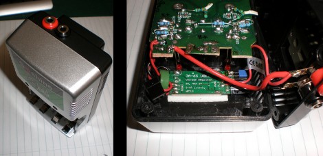
[Michael] took a battery charger meant to be connected to mains power and converted it to work with a solar panel. This was a traditional 4 cell charger which charges the batteries in pairs. He kept that functionality, but added USB charging with a special over-current feature. That’s because his Android phone has a fast and slow USB charging mode. The slow mode makes sure that it draws 500 mA or less to stay within USB specifications. But the fast mode draws more current when the phone detects that the USB connection is attached to a wall charger. [Michael] added a switch that patches a pull-up resistor to the data line, signaling to the phone that it’s okay to switch to fast charging mode.

As for the power supply itself, you can see that [Michael] snapped off the part of the circuit board that housed the original regulator. He’s added his own 5V switching regulator which offers a wide input voltage range. This is connected to two banana plug sockets which can be connected to the solar panel.

Running The Linux Kernel On A DE0-nano FPGA Board

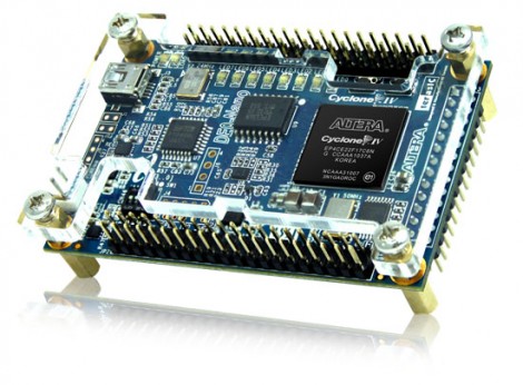
[Mike] has been filling up a rather intense wiki entry outlining how to run uClinux on a DE0-nano FPGA board. This is an inexpensive dev board that will run you somewhere between $80 and $100. Right off the bat he goes into a hefty list of the reasons that this is a foolish activity. To name a few: Once you’ve complete the build the device will be tethered for reboot.  This board doesn’t have Ethernet hardware and TCP/IP is one of the beast features of the uClinux kernel. And the FPGA tools are closed-source, which doesn’t often mesh with the ideals of Linux developers. But we still like to see what it really takes to get these large-scope firmware builds to compile and load correctly.

After his preamble you’ll find three main chunks. The first deals with setting up the toolchain on Fedora 14. From there, he installs packages necessary for cross-compiling, pulls down the source packages, and gets to work. Once the kernel is compiled and running on the FPGA [Mike] goes on to show you how to build out a simple hardware add-on in the form of a couple of LEDs connected to extra FPGA pins. The final portion of the wiki details rolling support for toggling the LEDs into the software distribution.

Arduino Boards Control Cheap Clockworks Via Coil Injection

Here’s a couple of clocks that use Arduino boards to control inexpensive clockworks. The concept is quite simple, and perhaps best outlined by [Matt Mets’] article on the subject. As it turns out, these clockworks are driven by a coil, forming a device that is quite similar to a stepper motor. If you solder a wire onto each end of the electromagnetic coil and hook those to a microcontroller, you can alter the speed at which the clock ticks. Just drive one pin high and the other low, then reverse the polarity for the next tick.

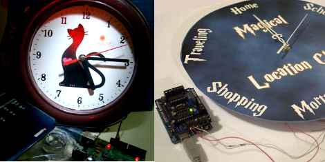
The clock you see on the right (translated) is a store-bought cheapy. The Arduino barely visible at the bottom of the image is sending pulses once every second. But as you can see in the video after the break, holding down a button will fast-forward through time. [Sodanam] posted his code as well as pictures of the hardware hack itself.

To the left is a horse of a different color. It’s a clock modeled after the Weasley household clock from the Harry Potter books. The clockwork trick is the same, but the Arduino uses GPS data and NOAA weather information to set the status.

Continue reading “Arduino Boards Control Cheap Clockworks Via Coil Injection”

DIY Breadboard Modules For Easy Prototyping

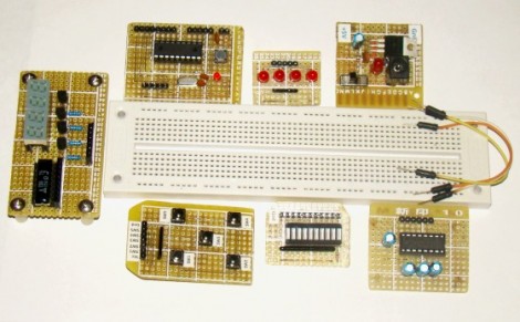
[Rajendra] got tired of building the same basic circuits time and again on the breadboard. He decided to build some simple, modular circuits on protoboard and make them easy to interface with the breadboard. As you can see, he ended up with seven modules that make prototyping faster and easier.

At first glance some might not seem all that beneficial. For instance, making a board for an 18-pin PIC microcontroller into a single-in-line form factor would seem like you’re actually wasting breadboard space when compared to the DIL package of the chip. But consider that the oscillator and its capacitors, reset button, and programming header are also on the breakout board and will not have to be built in place. There are also several I/O boards, one with five buttons, another with an LED bar graph, and a set of LEDs with a SIL resistor package on-board. These modules can be plugged into a breadboard and wired up with jumper wires, or connected directly to the same rows as the microcontroller module.

Two Dice, One 8-pin UC

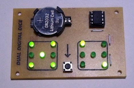
[Mike Shegedin] makes full use of an 8-pin microcontroller with this ATtiny13-based dice project. With a maximum of six I/O pins (that includes using the reset pin as I/O) he needed a couple of tricks in order to drive 14 LEDs and use a momentary push button for user input. We’re certainly familiar with the concepts here, but it still took quite a while to figure out what is going on with the schematic that [Mike] posted.

You’ve probably already guessed that he’s using Charlieplexing to drive more LEDs than he has pins. But when we started looking at the layout we thought he had drawn the schematic wrong, because there are six pairs of LEDs where the two diodes in each pair a not reverse biased, but hooked up in parallel. That, plus the fact that his battery is hooked up backwards. After several minutes of study the light bulb finally clicked on. Dice add pips (the dots on each side of a die) in pairs with the exception of the center pip. That means that you only need to control four total lines for each die (three pairs plus the center pip). There’s two ways to handle this, you could use four rows and two columns with traditional multiplexing, or you can reverse bias the two sets of LEDs for each die and use Charlieplexing. The former is a bit easier to program, the latter saves you one I/O pin and meant that [Mike] didn’t need to use the reset pin as I/O.

This is a clever addition to the collection of dice projects we’ve seen like the battery-less die, and the ATtiny2313 powered dice.