The motherboard of a Mattel Aquarius, with a small daughterboard mounted on top

Adding Composite Video To The Mattel Aquarius

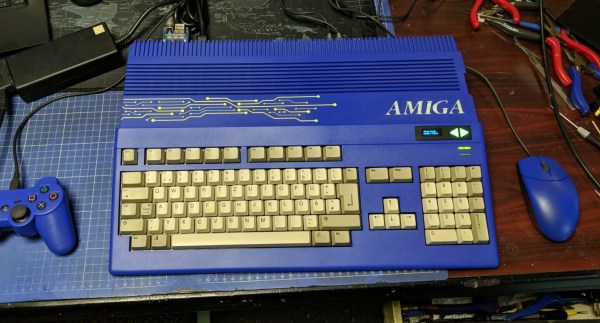
In the home computer market of the 1980s, there were several winners that are still household names four decades later: the Commodore 64, the Apple II and the Sinclair Spectrum, to name a few. But where there are winners, there are bound to be losers as well – the Mattel Aquarius being a good example. A price war between the bigger players, combined with a rather poor hardware design, meant that the Aquarius was discontinued just a few months after its introduction in 1983. However, this makes it exactly the type of obscure machine that [Leaded Solder] likes to tinker with, so he was happy to finally get his hands on a neat specimen listed on eBay. He wrote an interesting blog post detailing his efforts to connect this old beast to a modern TV.

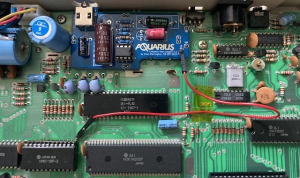
The main issue with the Aquarius is that it only has an RF video output, which results in a rather poor rendition of its already very limited graphics capabilities. Luckily, there is a fix available in the form of a composite A/V adapter that’s an almost plug-and-play upgrade. The only thing you need to do, as [Leaded Solder] illustrates in his blog post, is open up the computer, desolder the RF modulator and solder the A/V adapter in its place. Getting to that point was a bit tricky due to heavy EMI shields that were fixed in place with lots of solder, requiring liberal use of a desoldering iron. Continue reading “Adding Composite Video To The Mattel Aquarius”

A credit card-sized PCB with two sensing pads and a small OLED display

Card/IO Is A Credit Card-Sized, Open Source ECG Monitor

Of all the electrical signals generated by the human body, those coming from the heart are probably the most familiar to the average person. And because it’s also quite simple to implement the required sensors, it makes sense that electrocardiogram (ECG) machines are a popular choice among introductory medical electronics projects. [Dániel Buga], for instance, designed a compact ECG system the size of a credit card, cleverly dubbed Card/IO, that clearly demonstrates how to implement a single-lead ECG.

Although obviously not a medical-grade instrument, it still contains all the basic components that make up a proper biosignal sensing system. First, there are the sensing pads, which sense the voltage difference between the user’s two thumbs and simultaneously cancel their common-mode voltage with a technique called Right Leg Driving (RLD). The differential signal then goes through a low-pass filter to remove high-frequency noise, after which it enters an ADS1291 ECG analog front-end chip.

The ADS1291 contains a delta-sigma analog-to-digital converter as well as an SPI bus to communicate with the main processor. [Dániel] chose an ESP32-S3, programmed in Rust, to interface with the SPI bus and drive a 1″ OLED display that shows the digitized ECG signal. It also runs the user interface, which is operated using the ECG sensing pads: if you touch them for less than five seconds, the device goes into menu mode and the two pads become buttons to scroll through the different options.

All source code, as well as KiCad files for the board, can be found on the project’s GitHub page. If you’re just getting started in the biosensing field, you might also want check out this slightly more advanced project that includes lots of relevant safety information.

Continue reading “Card/IO Is A Credit Card-Sized, Open Source ECG Monitor”

A wooden frame with 64 green LEDs running a Game of Life simulation

Wooden CNC Sculpture Displays Conway’s Game Of Life

Conway’s Game of Life has been the object of fascination for computer hobbyists for decades. Watching the generations tick by is mesmerizing to watch, but programming the data structure and implementing the rules is also a rewarding experience, especially if you’re just getting acquainted with a new computing platform. Just as rewarding can be creating a nice piece of hardware to run the game on, as [SandwichRising] has just done: check out his beautiful wooden Game of Life implementation.

A set of PCBs implementing an 8x8 LED displayThe main part of his Game is a piece of poplar wood that was CNC routed to produce an 8×8 display adorned with neat chain-like shapes. The display consists of standard 5 mm green LEDs, but they’re not the things you see poking out the front of the wooden frame. Instead, what you’re seeing are 64 lenses made out of epoxy. [SandwichRising] first covered the holes with tape, then poured green epoxy into each one and waited for it to harden. He then took off the tape and applied a drop of UV-cured epoxy on top to create a lens.

All the LEDs are mounted on PCB strips that are hooked up to a central bus going to the main ATmega328P  microcontroller sitting on a separate piece of PCB. Whenever the system is powered on, the game is set to a random state determined by noise, after which the simulation begins. On such a small field it’s pretty common for the game to end up in a stable state or a regular oscillation, which is why the ATmega keeps track of the last few dozen states to determine if this has happened, and if so, reset the game to a random state again.

The source code, as well as .STL files for the PCBs and the frame, are available in the project’s GitHub repository. If woodworking isn’t your thing, there’s plenty of other ways to make neat Game of Life displays, such as inside an alarm clock, with lots of LEDS under a coffee table, or even with a giant flip-dot display.

A ZX Spectrum with a Microdrive emulator plugged into its expansion port

A Modern Replacement For The ZX Spectrum’s Odd Tape Storage System

Unless you were lucky enough to be able to afford a floppy disk drive, you probably used cassette tapes to store programs and data if you used pretty much any home computer in the 1980s. ZX Spectrum users, however, had another option in the form of the Microdrive. This was a rather unusual continuous-loop mini-tape cartridge that could store around 100 kB and load it at lightning speed, all at a much lower price point than a floppy drive. The low price came at the cost of poor durability however, and after four decades it’s becoming harder and harder to find cartridges that work reliably. [Derek Fountain] therefore set out to make a modern Microdrive emulator that stores data on SD cards.

Several projects already exist to replace Microdrives, but they typically also need the ZX Interface 1, a serial/network expansion module that’s becoming equally hard to find. Hence [Derek]’s choice to make his emulator a completely standalone system that directly plugs into the Spectrum’s expansion port.

A 3D-printed box with a PCB inside holding three Raspberry Pi Picos and an SD cardThe system is housed in a 3D-printed enclosure that holds two PCBs. Three Raspberry Pi Picos run the show inside: one to hold the ZX Interface 1’s ROM image and interface with the Spectrum’s bus, another to simulate the Microdrive, and a third to run the user interface and communicate with the SD card. The user can choose between eight tape images stored in .MDR format by using two pushbuttons and a rotary encoder, with a small OLED display showing the machine’s configuration.

While you might think that three dual-core 133 MHz ARM CPUs would run circles around the Spectrum’s Z80, it actually took quite a bit of work to get everyting running properly in real time. The 3.5 MHz bus clock rate gave the second Pico precious little time to fetch the required bytes out of its flash memory. Its RAM was fast enough for that, but too small to hold all eight tape images at the same time. In the end, [Derek] settled on using a separate 8 MB SPI DRAM chip that could easily keep up the data rate, with the Pi just using its GPIO ports to shuttle the data around.

All source code and extensive documentation are available on Derek’s excellent blog post and GitHub page. Be sure to also check out [Jenny]’s detailed review and teardown if you’d like to know more about the weird and wonderful Microdrive system.

Thanks for the tip, [Andrew]! Continue reading “A Modern Replacement For The ZX Spectrum’s Odd Tape Storage System”

An E-ink display showing Conway's Game of Life, with a solar cell beneath it

Solar Powered Game Of Life Follows The Sun’s Rhythm

Conway’s Game of Life is a beautiful example of how complex behavior can emerge from a few very simple rules. But while it uses biological terminology such as “cells”, “alive” and “generation”, the basic game is too simplistic to be a model for any real-world biological process. It’s easy to add features to make it a bit more life-like, however, as [David Hamp-Gonsalves] has done by giving the Conway’s creation something of a circadian rhythm.

The basic idea is that the speed at which [David]’s Game of Life evolves is governed by the amount of ambient light. The game runs off a solar cell that charges a battery, with the battery’s voltage determining how long it takes to advance the game by one generation. The system is therefore highly active in full sunlight, and grinds almost to a complete halt at night.

An ESP32 runs the simulation and outputs the result to a 400 x 300 pixel e-ink display. The display is extremely power-efficient by its very nature; the ESP’s main processor core, on the other hand, is deliberately placed into deep sleep mode most of the time to save as much power as possible. The Ultra Low Power (ULP) co-processor, meanwhile, keeps an eye on the lithium battery’s voltage as it’s slowly being charged by the solar cell. When the voltage reaches 3.3 V, the main CPU wakes up and computes the Game’s new state. In bright sunlight this happens every few seconds, while on an overcast day it could take minutes or even hours.

[David]’s interesting idea of changing Life‘s activity based on the amount of energy available turns the Game into something resembling a cold-blooded animal. We’ve seen a similar approach in a “solar creature” that runs a Life-life simulation on a seven-segment LCD. If it’s speed you care about however, you’re better off implementing Life in an FPGA.

A wooden spin coating machine sitting on a desk

Hackaday Prize 2023: Homebrew Spin Coater Makes Micrometer-Thin Layers

One of the great things about the Gearing Up challenge of the 2023 Hackaday Prize is that it lets you discover tools that you don’t encounter every day. We had never given much thought to spin coaters, for example, until we saw [Jeroen Delcour]’s neat homebrew example. As it turns out, spin coating has lots of applications in fields like optics, semiconductor manufacturing or even art projects, where a thin, even layer of a material is required on top of a flat substrate.

The basic idea behind a spin coater is simple: you dispense a few drops of a solution containing the material to be deposited on top of the thing you want to coat, then spin the thing around at a constant speed. The balance between the centripetal force and the liquid’s surface tension ensures that the liquid turns into a film with a consistent thickness all across the substrate. The solvent evaporates, and you’re left with a nice solid layer just a few microns thick.

[Jeroen] built his spin coater out of a brushless DC drone motor, a programmable motor controller, and an ESP32. A rotary pushbutton and an OLED form the user interface, allowing the user to select the speed and spin times. The electronics are all mounted inside a laser-cut wooden enclosure, with the motor sticking out the top, surrounded by a 3D-printed splash guard.

Professional spin coating equipment typically comes with a vacuum chuck to hold the sample in place, but [Jeroen] wasn’t too excited about implementing vacuum systems on a spinning platform and decided instead to simply clamp down the sample using screws in a laser-cut piece of acrylic. This works well enough, and is easy to customize for different sample sizes.

In the video embedded below, [Jeroen] experiments with applying a layer of silicone rubber onto a PCB. Spin coating is an essential step when you’re making your own semiconductor devices such as solar cells, though you might also need more complicated equipment such as an electron microscope. [Jeroen]’s spin coater is at least able to process much larger objects than one we saw earlier.

Continue reading “Hackaday Prize 2023: Homebrew Spin Coater Makes Micrometer-Thin Layers”

An Amiga 500 with a blue case and blue accessories

Restored Amiga 500 Is Blue – And Glows In The Dark

Few things are as satisfying to watch as a good retrocomputer restoration project – we’re always happy to see someone bring a rusty old Commodore, Apple or Atari back to life. The goal is typically to get the machine as close to its original state as possible, except for perhaps a few non-intrusive mods like memory upgrades. [Drygol] however, had already done this so many times that he thought it was time to take a different route for once, and apply some creativity to an old Amiga 500 case. Originalists may shudder, but we quite like his funky blue-and-yellow A500 mod.

An Amiga 500 with a poor blue-and-yellow paint job
Missing keys, random stickers and an ugly paint job: the A500 wasn’t looking great at the beginning

To be fair, [Drygol] wasn’t the first one to modify this specific Amiga’s case: one of its previous owners had already applied a rather shoddy blue paint job and defaced it with some stickers. [Drygol] decided to stick with the basic idea, but do it right this time. First he removed the old paint using concentrated lye, then gave it a fresh coat of blue. He also applied glow-in-the-dark paint to the Amiga logo embossed in the case and added a fluorescent yellow laser-cut circuit board ornament. It took a bit of experimenting to get all these elements just right, but the end result definitely looks the part.

The insides of the Amiga also needed some TLC: [Drygol] competely cleaned and lubricated the floppy drive, gave the motherboard a good ultrasonic scrub, and replaced dodgy capacitors all over. He expanded the RAM from 512 kB to 1 MB and added a Gotek floppy emulator, which can work in parallel with the original disk drive. To make the Gotek easy to operate, [Drygol] placed its OLED screen and a pair of touch-sensitive buttons in a cutout on the front of the case.

A matching blue mouse and gamepad, both connected through the MouSTer adapter, complete the setup. The result is a good-looking A500 with some modern conveniences that’s perfect for exploring the Amiga’s extensive software library. If custom colors aren’t your thing, you’ll be happy to know that the original shade of grey or beige might be available for your retro console, too.

Continue reading “Restored Amiga 500 Is Blue – And Glows In The Dark”