You’ll Never See The End Of This Project

…theoretically, anyway. When [Quinn] lucked into a bunch of 5 mm red LEDs and a tube of 74LS164 shift registers, a project sprang to mind: “The Forever Number,” a pseudo-random number generator with a period longer than the age of the universe. Of course, the components used will fail long before the sequence repeats, but who cares, this thing looks awesome!

Check out the gorgeous wire-wrapping job!

The core of the project is a 242-bit linear-feedback shift register (LFSR) constructed from (31) 74LS164’s. An XOR gate and inverter computes the next bit of the sequence by XNOR’ing two feedback bits taken from taps on the register, and this bit is then fed into bit zero. Depending on which feedback taps are chosen, the output sequence will repeat after some number of clock cycles, with special sets of feedback taps giving maximal lengths of 2N – 1, where N is the register length. We’ll just note here that 2242 is a BIG number.

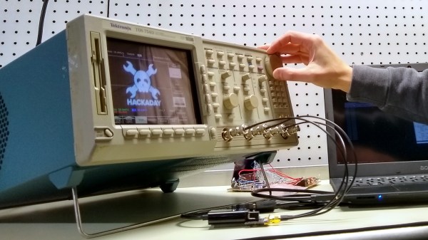
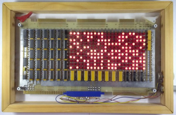
The output of the LFSR is displayed on a 22×11 array of LEDs, with the resulting patterns reminiscent of retro supercomputers both real and fictional, such as the WOPR from the movie “War Games,” or the CM2 from Thinking Machines.

The clock for this massive shift register comes from – wait for it – a 555 timer. A potentiometer allows adjustment of the clock frequency from 0.5 to 20 Hz, and some extra gates from the XOR and inverter ICs serve as clock distribution buffers.

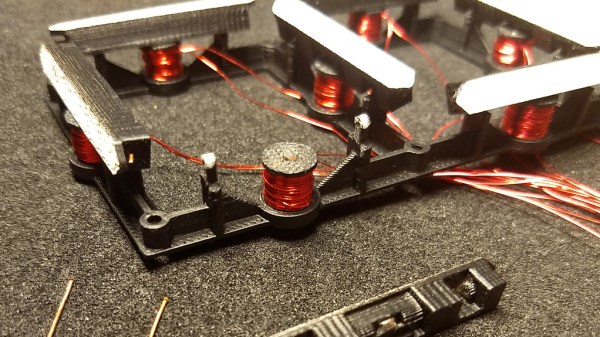
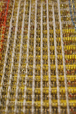
We especially love the construction on this one. Each connection is meticulously wire-wrapped point-to-point on the back of the board, a relic originally intended for an Intel SBC 80/10 system. This type of board comes with integrated DIP sockets on the front and wire-wrap pins on the back, making connections very convenient. That’s right, not a drop of solder was used on the board.

You can see 11 seconds of the pattern in the video after the break. We’re glad [Quinn] didn’t film the entire sequence, which would have taken some 22,410,541,156,499,040,202,730,815,585,272,939,064,275,544, 100,401,052,233,911,798,596 years (assuming a 5 Hz clock and using taps on bits 241 and 171 ).

Continue reading “You’ll Never See The End Of This Project”

Sharpest Color CRT Display Is Monochrome Plus A Trick

I recently came across the most peculiar way to make a color CRT monitor. More than a few oscilloscopes have found their way on to my bench over the years, but I was particularly struck with a find from eBay. A quick look at the display reveals something a little alien. The sharpness is fantastic: each pixel is a perfect, uniform-colored little dot, a feat unequaled even by today’s best LCDs. The designers seem to have chosen a somewhat odd set of pastels for the UI though, and if you move your head just right, you can catch flashes of pure red, green, and blue. It turns out, this Tektronix TDS-754D sports a very peculiar display technology called NuColor — an evolutionary dead-end that was once touted as a superior alternative to traditional color CRTs.

Join me for a look inside to figure out what’s different from those old, heavy TVs that have gone the way of the dodo.

Continue reading “Sharpest Color CRT Display Is Monochrome Plus A Trick”

ULX3S: An Open-Source Lattice ECP5 FPGA PCB

The hackers over at Radiona.org, a Zagreb Makerspace, have been hard at work designing the ULX3S, an open-source development board for LATTICE ECP5 FPGAs. This board might help make 2019 the Year of the Hacker FPGA, whose occurrence has been predicted once again after not quite materializing in 2018. Even a quick look at the board and the open-source development surrounding it hints that this time might be different.

Bottom side of ULX3S PCB

The ULX3S was developed primarily as an educational tool for undergraduate-level digital logic classes. As such, it falls into the “kitchen sink” category of FPGA boards, which include a comprehensive suite of peripherals and devices for development, as opposed to more bare-bones FPGA breakouts. The board includes 32 MB SDRAM, WiFi via an ESP-32 (supporting over-the-air update), a connector for an SPI OLED display, USB, HDMI, a microSD slot, eight channels of 12-bit ADC (1 MS/s), a real-time-clock, 56 GPIO pins, six buttons, 11 LEDs, and an onboard antenna for 433 MHz FM/ASK. This seems like a great set of I/Os for both students and anyone else starting FPGA development.

The ULX3S supports members of the Lattice ECP5 FPGA family, ranging from the 12F (12 k LUTs) to the 85F (84 k LUTs). What can you do with this much FPGA horsepower? Have a look at the long list of examples curated in the ULX3S Links repo. There, you’ll find code from retro-computing to retro-gaming, the usual LED and HDMI demos, and even Linux running on a mor1kx OpenRISC core. Maybe the most interesting links in the repo, however, are those that show how to program the FPGA with a completely open-source toolchain. Proprietary toolchains are the last link keeping some vendor’s FPGAs from wider adoption in the OSHW community, and it’s great to see people chipping away at them.

The board itself is completely open-source. In the GitHub repo, you’ll find the KiCAD 5 design files for the PCB released under an MIT-style license. Even more impressive is the advice in the README, which not only welcomes independent production of the boards, but gives some solid advice on dealing with PCBA vendors during manufacture. Our own advice is to do the right thing and offer the developers a cut if you decide to independently market this board, even though you aren’t required to by the license. If want one, but don’t want to manufacture your own, you can contact the developers using the email or gitter links at the bottom of the ULX3S page: they’re currently doing a small production run.

The Radiona Org folks have created a few videos showcasing example code. Check out how the on-board ESP-32 runs a web server that can load bitstreams into the FPGA (in this case for some retro-gaming), after the break.

Continue reading “ULX3S: An Open-Source Lattice ECP5 FPGA PCB”

DIY Guided Telescope Mount Tracks Like A Barn Door

Astrophotography is an expensive hobby. When assembling even a basic setup consisting of a telescope, camera, guiding equipment and mount, you can easily end up with several thousand dollars worth of gear. To reduce the monetary sting a little, [td0g] has come up with an innovative homebrew mount and guiding solution that could be assembled by almost any dedicated amateur, with the parts cost estimated around $100. The accuracy required to obtain high-quality astrophotographs is quite demanding, so we’re impressed with what he’s been able to achieve on a limited budget.

The inspiration for this design comes from an incredibly simple star tracking device known as a barn-door tracker, or Haig mount. Invented by George Haig in the 1970’s, this mount is essentially nothing more than a hinge aligned with the Earth’s axis of rotation. A threaded rod or screw, turned at a constant rate, is used to slowly open the hinge so that a mounted camera tracks the apparent motion of the heavens. As a result, long exposures can show pinpoint images of stars and sharp details of deep-sky objects, instead of curved star trails. [td0g] adapted this technique to drive a more traditional telescope mount, using barn-door-like drive screws on both the right ascension and declination axes. A pair of NEMA 17 stepper motors drive 4-mm pitch Acme threaded rods through toothed pulleys 3D printed from PETG.

Speaking of 3D-printed parts, this build is a good example of judicious use of the technology: where metal parts are warranted, metal parts are used, and printed plastic is relegated to those places where it can adequately do the job. [td0g] has placed the STL files for the printed parts on Thingiverse in case you want to replicate the drive.

The non-linear relationship between the threaded rod rotation and right ascension drive rate usually limits the length of exposure you can reasonably achieve with a barn-door tracker. To adjust for this, [td0g] created a lookup table in firmware to compensate the drive and allow longer exposures. He mentions that the drive will operate for three hours before it hits the end of the screw’s travel and needs to be reset, but if he can manage three hour exposures, his skies must be much darker than ours!

Continue reading “DIY Guided Telescope Mount Tracks Like A Barn Door”

Electromagnetic 7-Segment Display Easy On The Eyes AND The Ears

We love electromagnetic displays: take the modern look of a digital readout, combine with the low-tech coil mechanism that you theoretically could create yourself, add a dash of random clacking sounds, and what’s not to like? Evidently, [Nicolas Kruse] shares our affection for these displays, because he’s taken it beyond theory and created a 7-segment magnetically-actuated display from scratch.

The display is 3D-printed, as you would expect these days. Each segment contains a small neodymium magnet, and each coil a 1 mm iron core for flux concentration. The coils are driven with a 1.6 A peak current, causing the segments to flip in less than 10 ms. [Nicolas] provides STL files for the display base, segments, and spools so you can print your own display. He’s also released the schematics and code for the driver, which uses an ATtiny44 to drive the coils through N- and P-channel MOSFETs. Initially designed to drive a passive 4×7 matrix of displays, the driver couldn’t quite manage to flip one segment without affecting its neighbors. However, for a single display, the driver works fine. We hope he figures out the matrix issue soon, because we really want to see a clock made with these displays.

You can see (and hear) a short video of the display in action after the break. The clacking does not disappoint!

Continue reading “Electromagnetic 7-Segment Display Easy On The Eyes AND The Ears”

Program This Badge In Lisp

This hardware badge is a computer programmed with Lisp. You can write your own programs right on the badge using the built-in keyboard, as long as you know Lisp.

If there’s one thing we really like to see, it’s people advancing their own projects based on inspiration from others. The Lisp Badge by [David Johnson-Davies] is a perfect example. With an interface inspired by [Voja Antonic’s] hardware design for the 2018 Hackaday Belgrade Conference Badge, this version is an upgrade of an earlier single-board Lisp machine, now sporting an integrated keyboard.

Unlike the Belgrade badge, which is programmed in BASIC, this new badge is programmed in uLisp, a subset of common lisp designed for microcontrollers. Let’s face it, BASIC is retro, but Lisp is even more so, only pre-dated by FORTRAN as the oldest high-level language. So, if you’re into retro-style programming on small devices (physically small, that is), you should consider building one of these.

A 16 MHz ATmega 1284P serves as the badge’s brain, allowing storage for 2,816 Lisp cells, while the 256×64 pixel OLED display shows 8 lines of 42 characters in 16 gray levels. A full complement of I/O connections includes four analog inputs, two analog outputs, I2C, SPI, serial, and a handful of GPIOs for interfacing with just about anything. Power comes from a LiPO battery, which at a nominal voltage of 3.7 V doesn’t quite meet the datasheet requirements for running the processor at 16 MHz, although it seems to work fine in practice. Really cautious builders could opt for a 12 MHz crystal transplant to avoid any possibility of problems.

The keyboard layout is optimized for uLisp programming: unnecessary keys have been removed and the all-important parenthesis are afforded their own dedicated keys on the bottom row. This is presumably for convenience of use, but we suspect this will also make it easier to replace the parenthesis key switches when they inevitably wear out from overuse [obligatory Lisp/parenthesis joke].

As far as entering uLisp programs, you can simply use the keyboard. The built-in editor buffers a full screen of text, and includes parenthesis matching that highlights each pair as you type. We’re guessing that we won’t see Emacs implemented in the near future, so this bracket management is a great feature for a badge-based editor. If you find the keyboard difficult to type on, you can also enter programs over the serial port.

The other thing we really like to see is open-source projects. [David] doesn’t let us down on this point, either. The Eagle design files for the PCB as well as the source code for the badge are available on GitHub. The PCB is also shared on OSH Park, and there are detailed instructions for installing the bootloader and uploading the code.

If programmable badges is your thing, also check out the 2018 Hackaday Supercon Badge, the successor the Belgrade design.

Thanks to [Sven] for the tip!

Peering Into A Running Brain: SDRAM Refresh Analyzed From Userspace

Over on the Cloudflare blog, [Marek] found himself wondering about computer memory, as we all sometimes do. Specifically, he pondered if he could detect the refresh of his SDRAM from within a running program. We’re probably not ruining the surprise by telling you that the answer is yes — with a little more than 100 lines of C and help from our old friend the Fast Fourier Transform (FFT), [Marek] was able to detect SDRAM refresh cycles every 7818.6 ns, lining right up with the expected result.

The “D” in SDRAM stands for dynamic, meaning that unless periodically refreshed by reading and writing, data in the memory will decay. In this kind of memory, each bit is stored as a charge on a tiny capacitor. Given enough time (which varies with ambient temperature), this charge can leak away to neighboring silicon, turning all the 1s to 0s, and destroying the data. To combat this process, the memory controller periodically issues a refresh command which reads the data before it decays, then writes the data back to fully charge the capacitors again. Done often enough, this will preserve the memory contents indefinitely. SDRAM is relatively inexpensive and available in large capacity compared to the alternatives, but the drawback is that the CPU can’t access the portion of memory being refreshed, so execution gets delayed a little whenever a memory access and refresh cycle collide.

Chasing the Correct Hiccup

[Marek] figured that he could detect this “hiccup,” as he calls it, by running some memory accesses and recording the current time in a tight loop. Of course, the cache on modern CPUs would mean that for a small amount of data, the SDRAM would never be accessed, so he flushes the cache each time. The source code, which is available on GitHub, outputs the time taken by each iteration of the inner loop. In his case, the loop typically takes around 140 ns.

Hurray! The first frequency spike is indeed what we were looking for, and indeed does correlate with the refresh times.

The other spikes at 256kHz, 384kHz, 512kHz and so on, are multiplies of our base frequency of 128kHz called harmonics. These are a side effect of performing FFT on something like a square wave and totally expected.

As [Marek] notes, the raw data doesn’t reveal too much. After all, there are a lot of things that can cause little delays in a modern multitasking operating system, resulting in very noisy data. Even thresholding and resampling the data doesn’t bring refresh hiccups to the fore. To detect the SDRAM refresh cycles, he turned to the FFT, an efficient algorithm for computing the discrete Fourier transform, which excels at revealing periodicity. A few lines of python produced the desired result: a plot of the frequency spectrum of the lengthened loop iterations. Zooming in, he found the first frequency spike at 127.9 kHz, corresponding to the SDRAMs refresh period of 7.81 us, along with a number of other spikes representing harmonics of this fundamental frequency. To facilitate others’ experiments, [Marek] has created a command line version of the tool you can run on your own machine.

If this technique seems familiar, it may be because it’s similar the the Rowhammer attack we covered back in 2015, which can actually change data in SDRAM on vulnerable machines by rapidly accessing adjacent rows. As [Marek] points out, the fact that you can make these kinds of measurements from a userspace program can have profound security implications, as we saw with the meltdown and spectre attacks. We have to wonder what other vulnerabilities are lying inside our machines waiting to be discovered.

Thanks to [anfractuosity] for the tip!