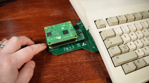
The synth in question in its acrylic case.

DIY Polyphonic Synth Sings In 8-Part Harmony

There’s just something about an analog synthesizer. You’d think that for electronic music, digital sampling would have totally taken over by now, but that’s really not true. The world of analog synths is alive and well, and [Polykit] has a new, open-source polyphonic synthesizer to add to the ever-growing chorus of electronic instruments.

The analog part is thanks to the eight identical voice cards that plug into the machine’s mainboard: each one has a voltage controlled oscillator to generate tones, an envelope generator, multiple voltage-controlled amplifiers, and even a pole mixing filter which is also, yes, voltage controlled. Each voice card outputs stereo, and yes, there are controllable mixing circuits for left and right output.

All that voltage control means a lot of lines from digital-to-analog converters (DACs), because while this is an analog synth, it does have a MIDI interface, and that means that a microcontroller needs to be able to speak voltage. In this case, the brains are an ATmega2560. Instead of stacking the board with enough expensive DACs to interpret the MCU’s digital signals, [Polykit] is instead is using some clever tricks to get more work out of the one DAC he has. Some things get tied together on all eight voices, like the envelope parameters; other values are run through a demultiplexer to make the most possible use of the analog lines available. Of course that necessitates some latching circuitry to hold the demuxed values on those lines, but it’s still cheaper than multiple high-quality DACs.

It’s a well-thought out bit of kit, down to the control panel and acrylic case, and the writeup is worth reading to get the full picture. The voice cards, main board and control board all have their own GitHub repositories you can find at the bottom of the main page. If you’re into video, [Polykit] has a whole series on this project you might want to check out on Makertube; we’ve embedded the first one below.

If you want to get your toes wet in the wonderful world of synthesizers, this library of seventy synths is an amazing place to start, because it has great simple projects.

Thanks to [Polykit] for the tip!

Continue reading “DIY Polyphonic Synth Sings In 8-Part Harmony”

DIY TENS Machine Is A Pain-Relief PCB

Transcutaneous Electrical Nerve Stimulation (TENS) is one of those things that sounds like it must be woo when you first hear of it. “A trickle of current that can deal with chronic pain better than the pills we’ve been using for decades? Yeah, and what chakras do you hook this doo-hickie up to?” It seems too good to be true, but in fact it’s a well-supported therapy that has become part of scientific medicine. There are no crystals needed, and you’re applying electrodes to the effected area, not your chakras. Like all medical devices, it can be expensive if you have to buy the machine out-of-pocket… but it is just a trickle of current. [Leon Hillmann] shows us its well within the range of hackability, so why not DIY?

[Leon]’s TENS machine is specifically designed to help a relative with hand problems, so breaks out electrodes for each finger, with one on the palm serving as a common ground. This type of TENS is “monophasic”– that is, DC, which is easier than balancing current flowing in two directions through quivering flesh. The direct current is provided at 32 V to the digit electrodes, safely kept to a constant amperage with a transistor-based current limiting circuit. The common ground in the palm is pulsed at a rate set by an ATmega32U4 and thus controllable: 14 Hz is given as an example.

Obviously if you want to reproduce this work you’re doing it at your own risk and need to consult with relevant medical professionals (blah blah blah, caveat gluteus maximus) but this particular sort of medical device is a good fit for the average hacker. Aside from prosthetics, we haven’t seen that much serious medical hacking since the pandemic. Still, like with synthesizing medical drugs, this is the kind of thing you probably don’t want to vibe code.

Wiring Up The Railway, All The Live-Long Day

For those of you who haven’t spent time in North America around this time of year, you may be unaware of two things: one, the obligatory non-stop loop of “All I Want For Christmas Is You” retail workers are subjected to starting November first, and two: there is a strong cultural association between Christmastime and model railroading that may not exist elsewhere. That may down to childhood memories of when we got our first trainsets, or an excellent postwar marketing campaign by Lionel. Either way, now that Mariah Carey is blaring, we’re thinking about our holiday track layouts. Which makes this long presentation on Wiring for Small Layouts by [Chicago Crossing Model Railroad] quite timely.

There are actually three videos in this little course; the first focuses mostly on the tools and hardware used for DCC wiring (that’s Digital Command Control), which will be of less interest to our readers– most of you are well aware how to perform a lineman’s splice, crimp connectors onto a wire, and use terminal blocks.

The second two videos are actually about wiring, in the sense of routing all the wires needed for a modern layout– which is a lot more than “plug the rheostat into the tracks in one spot” that our first Lionel boxed set needed. No, for the different accessories there are multiple busses at 5V, 12V and 24V along with DCC that need to be considered. Unsurprisingly enough given those voltages, he starts with an ATX power supply and breaks out from there.

Even if you’re not into model railroading, you might learn something from these videos if you haven’t done many projects with multiple busses and wire runs before. It’s far, far too easy to end up with a rats nest of wires, be they DCC, I2C or otherwise. A little planning can save some big headaches down the line, and if this is a new skill for you [Chicago Crossing Model Railroad] provides a good starting point for that planning. Just skip ahead a couple minutes for him to actually start talking if you don’t want the musical cliff notes montage at the start of the videos.

If you don’t have any model trains, don’t worry, you can 3D print them.  Lack of room isn’t really an excuse.

Continue reading “Wiring Up The Railway, All The Live-Long Day”

Commodore’s Most Popular Computer Gets DOOM-style Shooter

When people talk about the lack of a DOOM being the doom Commodore home computers, they aren’t talking about the C64, which was deep into obsolescence when demon-slaying suddenly became the minimal requirement for all computing devices. That didn’t stop [Kamil Wolnikowski] and [Piotr Kózka] from hacking together Grey a ray-cast first-person shooter for the Commodore 64.

Grey bares more than a passing resemblance to id-software’s most-ported project. It apparently runs at 16 frames per second on a vanilla C64 — no super CPU required. The secret to the speedy game play is the engine’s clever use of the system’s color mapping functionality: updating color maps is faster than redrawing the screen. Yeah, that makes for rather “blockier” graphics than DOOM, but this is running on a Commodore 64, not a 386 with 4 MB of RAM. Allowances must be made. Come to think of it, we don’t recall DOOM running this smooth on the minimum required hardware — check out the demo video below and let us know what you think.

The four-level demo currently available is about 175 kB, which certainly seems within the realms of possibility for disk games using the trusty 1541. Of course nowadays we do have easier ways to get games onto our vintage computers.

If you’re thinking about Commodore’s other home computer, it did eventually get a DOOM-clone. Continue reading “Commodore’s Most Popular Computer Gets DOOM-style Shooter”

Wear This RISC V, RPN Calculator Watch For Maximum Nerd Cred

Once upon a time, owning a calculator watch was the epitome of cool. Well, for a very specific subset of the population with our own definition of “cool” anyway. The only thing cooler than wearing a calculator watch? Making a calculator watch, of course! If you do it as part of developing your own SDK for a popular RISC V microcontroller, all the better. That’s what [Miroslav Nemecek] did with his Antcalc watch, which is one of the demo projects for the CH32Lib SDK, which is currently under development at version 0.35 as this is written.

It appears as though the solid core wire on the back of the homemade PCB is used to hold the watch band, a nice little hack.

As you might guess, CH32LibSDK is targeting the super-cheap CH32 series of RISC V microcontrollers. Perhaps because the SDK is so early in development, there’s not much documentation outside of the example projects. The examples are all worth looking at, but our tipster wanted us to cover the Antcalc calculator watch specifically.

The Antcalc watch uses the SOP16-packaged CH32V002A4M6 to drive a small OLED display while taking input in Reverse Polish Notation from a dozen small buttons. We’re not sure how the cool kids feel about RPN these days, but that’s got to be worth extra nerd cred. Using a RISC V chip doesn’t hurt in that department, either.

For something so small– 30 mm x 55 mm–it’s looks like a decent little calculator, with 10 registers holding a mantissa of 21 digits and exponents up-to +/-99 in binary coded decimal. Seven layers on the dozen-key input pad mean most of the scientific functions you could ask for are available, along with the ability to record and replay upto 10 macros. There are also ten memory slots, all of which go into the chip’s onboard flash so are non-volatile during a battery swap. (Of which many will be necessary, since this appears to run on a single coin cell.)

If you get bored of wrist-mounted calculating, you could always repurpose this microcontroller to play MOD files on your wrist. Some people couldn’t imagine ever getting bored by a wrist-mounted calculator, and just for them we have this teardown of a beautiful 1975 model and a this article on the history of the calculator watch.

Thanks to [James Bowman] for the tip.

Diskette Game Floppy Flopper Is Certainly No Flop

There’s a tactile joy to the humble 3.5″ floppy that no USB stick will ever match. It’s not just the way they thunk into place in a well-made drive, the eject button, too, is a tactile experience not to be missed. If you were a child in disk-drive days, you may have popped a disk in-and-out repeatedly just for the fun of it — and if you weren’t a child, and did it anyway, we’re not going to judge. [igor] has come up with a physical game called “Floppy Flopper” that provides an excuse to do just that en masse, and it looks like lots of fun.

It consists of nine working floppy drives in a 3×3 grid, all mounted on a hefty welded-steel frame. Each drive has an RGB LED above it. The name of the game is to swap floppies as quickly as possible so that the color of the floppy in the drive matches the color flashing above it. Each successful insertion is worth thirteen points, tracked on a lovely matrix display. Each round is faster than the last, until you miss the window or mix up colors in haste. That might make more sense if you watch the demo video below.

Continue reading “Diskette Game Floppy Flopper Is Certainly No Flop”

Amiga? Arduino? AMeagerBall Gets The Uno Bouncing

When the iconic “Boing Ball” first debuted 40 years ago, it was a wonder to behold. There was nothing like it in the home compuing world upto that time, and it showed that Commodore’s new “Amiga” was a powerhouse sure to last the test of time. Forty years later, the Amiga as we knew it then might not be with us anymore, but [Mark Wilson] is recreating its iconic demo on a microcontroller– but not just any microcontroller. “AMeagerBall” is an Arduino Uno exclusive, and it even tells the time.

Like the original “Boing Ball”, the demo is running at 320×240, though on a touch LCD shield instead of a CRT. Unlike some microcontrollers, the Uno doesn’t have the horsepower to just brute-force emulate a 1980s home computer, so [Mark] has had to recreate the boing ball from scratch. He’s not doing it with any graphics libraries, either. On the Uno that would be too slow, so [Mark] is driving the LCD directly to its appropriate registers, to stay close enough to the metal to make it work. That means if you’re going to try the code on his GitHub repository, you’ll need to be sure to use matching hardware or be prepared to port it.

One of the things about Amiga’s demo that was so impressive is that it hardly made use of the CPU, allowing the Workbench to be pulled up while the ball bounced. That’s not the case here, as the UNO doesn’t have any extra graphics chips. Still, [Mark] was able to squeeze enough horsepower out of everyone’s favourite ATmega to present us with an Amiga-styled clock– either analog, digital, or in the workbench title bar in that iconic blue-and-white. To keep the clock accurate, he’s squeezed an RTC module in, too. Lovely! The different clocks can be accessed via the touchscreen.

Oh, did we forget to mention that the touchscreen is implemented? This certainly stretches the hardware far enough to be considered a demo. If just a bouncing ball doesn’t work the UNO hard enough for you, try booting Linux.

This isn’t the first bouncing ball demo we’ve seen on a microcontroller:  here are four of them bouncing in an ATtiny85.

Continue reading “Amiga? Arduino? AMeagerBall Gets The Uno Bouncing”