Bionic Implants Can Go Obsolete And Unsupported, Too

When a piece of hardware goes unsupported by a company, it can be frustrating. Bugs may no longer get fixed, or in the worst cases, perfectly good hardware can stop working entirely as software licences time out. Sadly, for a group reliant on retinal implants from company Second Sight, the company has since stopped producing and supporting the devices that give them a crude form of bionic sight.

The devices themselves consist of electrodes implanted into the retina, which can send signals to the nervous system which appear as spots of light to the user. A camera feed is used to capture images which are then translated into signals sent to the retinal electrodes. The results are low-resolution to say the least, and the vision supplied is crude, but it gives users that are blind a rudimentary sense that they never had before. It’s very much a visual equivalent to the cochlear implant technology.

The story is altogether too familiar; Second Sight Medical Products came out with a cutting-edge device, raised money and put it out into the world, only to go bankrupt down the road, leaving its users high and dry. Over 350 people have the implants fitted in one eye, while one Terry Byland is the sole person to have implants in both his left and right eyeballs. Performance of the device was mixed, with some users raving about the device while others questioned its utility.

Continue reading “Bionic Implants Can Go Obsolete And Unsupported, Too”

Here’s How Those Battery-Free Flashing Phone Stickers Worked

The late 90s and early 2000s were a breakout time for mobile phones, with cheap GSM handsets ushering in the era in which pretty much everybody had a phone. Back then, a popular way to customize one’s phone was to install a sticker that would flash when the phone rang. These required no batteries or any other connection to the phone, and [Big Clive] has dived in to explain how they worked. 

The simple schematic of the flashing sticker circuit. The flashing was generated by the pulses of RF energy from the smartphone.

It’s an old-fashioned teardown that requires a bit of cutting to get inside the sticker itself. A typical example had three LEDs in series for a total voltage drop of around 7V, hooked up to two diodes and a PCB trace antenna. A later evolution used raw unpackaged components bonded to the PCB. Future versions went down to a single diode, using the LEDs to serve as the second. The basic theory was that the PCB traces would pick up RF transmitted by the phone when a call was coming in, lighting the LEDs.

In the 2G era, the freuqencies used were on the order of 300 MHz to 1.9GHz. A combination of the change in frequencies used by modern phone technology and the lower transmit powers used by handsets means that the stickers don’t work properly with modern phones according to [Big Clive].

Incidentally, you might like to consider running your own old-school cellphone network. Video after the break.

Continue reading “Here’s How Those Battery-Free Flashing Phone Stickers Worked”

Hacking An Extra SATA Port Into A Thin Client

Thin clients were once thought by some to be the future of computing. These relatively low-power machines would rely on large server farms to handle the bulk of their processing and storage, serving only as a convenient local way for users to get access to the network. They never quite caught on, but [Jan Weber] found an old example and set about repurposing it as a NAS.

The Fujitsu Futro S900 was built up to 2013, and only had one SATA port from the factory. [Jan] wanted to add another as this would make the device more useful as a network attached storage server.

The motherboard design was intended primarily for industrial control or digital signage applications, and thus has plenty of interfaces onboard. [Jan]’s first target was some unpopulated footprints for SATA ports onboard, but after soldering on a connector, it was found that the BIOS wouldn’t recognise the extra ports anyway.

However, after reflashing the BIOS with one from an alternate model, the port worked! The system also seemed to then imagine it was connected to many additional LAN interfaces, but other than that glitch, the hack is functional. Now, with a pair of 2 TB SSDs inside, the S900 is a great low-power NAS device that can store [Jan]’s files.

It’s a tidy hack, and one that will likely appeal to those who prefer to run their own hardware rather than relying on the cloud. If you’re working on your own innovative NAS project, be sure to let us know!

3D Printed Suncatcher Shines In The Light

Diffraction gratings create beautiful rainbow patterns when interacting with natural white light, and [audreyobscura] was familiar with their properties.  Thus, she set about producing an attractive 3D-printed suncatcher ornament that positively shines in the sun.

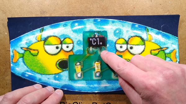
The design is straightforward, consisting of a 3D printed frame made of pieces glued together using QuickGrab glue. The pieces come together into a 7-segment star design, with a subtle 3D structure to it which helps add strength in addition to looking good.

Once assembled, sections of plastic diffraction grating are cut to size using a Curio desktop cutter. These are then glued into each segment of the star. While it’s possible to 3D print pieces with diffraction-grating like effects, using the film in this way allows light to pass through the suncatcher to create a more impressive effect.

On a cloudy day, the suncatcher looks almost entirely unassuming. However, when Earth’s nearest star shines, it projects glorious rainbows throughout the room, and letting it sway in the breeze lets the light play across the walls.

It’s a nice build, and a relatively easy ornament to make even if you’re new to 3D printing. We do like a good bit of decoration around here, especially if it’s a tiny version of a real TV. Video after the break.

Continue reading “3D Printed Suncatcher Shines In The Light”

A Gameport Joystick To USB-MIDI Converter

These days, live music performance often involves electronic synthesizers and computers rather than traditional instruments played by hand. To aid in his own performances, [alekappa] built a special interface to take signals from a joystick and convert them to MIDI messages carried over USB.

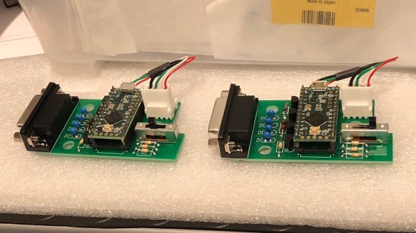
The build is simple and straightforward, using a Teensy LC to interface with a simple gameport joystick. With a smattering of simple components, it’s easy to read the outputs of the joystick with only a little debounce code needed to ensure the joystick’s buttons are read accurately. Similarly, analog axes are read using the analog-to-digital converters onboard the microcontroller.

This data is then converted into control changes, note triggers and velocity levels and sent out over the Teensy LC’s USB interface. A mode switch enables changes to the system’s behaviour to be quickly made. The device is wrapped up in a convenient housing nabbed from an old Gameport-to-USB converter from many years ago.

It’s a neat project and we’re sure the joystick allows [alekappa] to add a new dimension to his performances on stage. We’ve seen other great MIDI controllers, too, from the knitted keyboard to the impressive Harmonicade. If you’ve got your own mad musical build under construction, don’t hesitate to drop us a line!

Remoticon 2021 // Joey Castillo Teaches Old LCDs New Tricks

Segmented liquid crystal displays are considered quite an old and archaic display technology these days. They’re perhaps most familiar to us from their use in calculators and watches, where they still find regular application. [Joey Castillo] decided that he could get more out of these displays with a little tinkering, and rocked up to Remoticon 2021 to share his findings.

[Joey’s] talk is a great way to learn the skills needed to reverse engineer a typical segment LCD.
[Joey] got his start hacking on these displays via his Sensor Watch project –  a board swap for the venerable Casio F-91W wristwatch, with the project now available on CrowdSupply. It kits out the 33-year-old watch design with a modern, low-power ARM Cortex M0+ microcontroller running at 32 MHz that completely revolutionizes what the watch can do. Most importantly, however, it repurposes the watches original segmented monochrome LCD.

Segment LCDs are usually small monochrome devices made out of glass, that have the benefit of using very little power in their operation. They come with a fixed layout, which cannot be changed – so they’re often designed specifically for a given purpose. A calculator will have segments laid out to display numbers, often in the usual 7-segment fashion, while a watch may add dedicated segments for displaying things like “AM,” “PM,” or “ALARM.” Continue reading “Remoticon 2021 // Joey Castillo Teaches Old LCDs New Tricks”

How To Get Your Diffraction Grating 3D Prints Right The First Time

Diffraction gratings are beautiful things, bending transmitted and reflected light and splitting it into its component wavelengths to create attractive iridescent rainbow patterns. It’s the same effect you see on the bottom of a CD!

You can 3D print a functional diffraction grating, too, with the right techniques, as it turns out! The average 3D printer can’t recreate the tiny-scaled patterns of a diffraction grating directly; a typical diffraction grating may have up to 1000 lines per mm. Instead, by 3D printing onto an existing diffraction grating, the print can pick up the texture on its base layer. It’s a great way to add iridescence and shine to a print.

We’ve seen similar work before, but the guide from [All3DP] goes into greater detail on how to get the effect to work just right. Getting the bed as close to perfectly level is key here, as is the first layer height. This is because the first layer of plastic has to meld perfectly with the diffraction grating to pick up the pattern. Too high and the grooves won’t transfer to the plastic, and too low, and it’s likely you’ll just melt the grating itself. Setting the Z-offset appropriately can help here.

Choosing the right bed temperature is also important to ensure the molten plastic is able to flow into the grooves of the grating. Again, the temperature at which the diffraction grating itself can survive is important to take into account; going above 90 degrees can be risky here. The guide also shows two methods of achieving the goal: one can either use an off-the-shelf grating, or one can prepare a no-longer-wanted CD into a suitable print surface.

Naturally, removing the print must be done delicately, lest one disturb the delicate structures key to generating the iridescent effect. [All3DP] recommends using a freezer to help separate the parts from the grating surface. It also bears noting that the print won’t survive excessive handling, as the grating structures will get damaged by physical touch.

It’s a great in-depth guide on how to get diffraction grating prints right. Meanwhile, consider diving deeper into the world of 3D printed optics!