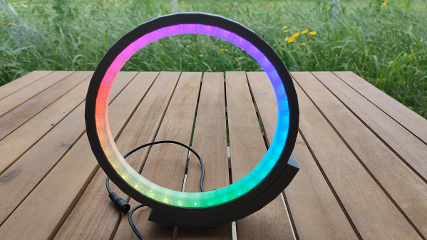
Classic Film Camera Goes Digital With Game Boy Tech

Despite having been technologically obsolete for a decade or two, analog photography is still practiced by hobbyists and artists to achieve a particular aesthetic. One might imagine a similar thing happening with early digital cameras, and indeed it has: the Game Boy Camera has seen use in dozens of projects. [Michael Fitzmayer] however decided to combine the worlds of analog and early digital photography by equipping a Holga with the image sensor from a Game Boy Camera.

A camera module and an STM32 module on a solderless breadboardThe Holga, if you’re not familiar, is a cheap film camera from the 1980s that has achieved something of a cult following among retro-photography enthusiasts. By equipping it with the sensor from what was one of the first mass-market digital cameras, [Michael] has created a rather unusual digital point-and-shoot. The user interface is as simple as can be: a single button to take a photo, and nothing else. There’s no screen to check your work — just as with film, you’ll have to wait for the pictures to come back from the lab.

The sensor used in the Game Boy Camera is a Mitsubishi M64282FP, which is a 128 x 128 pixel monochrome CMOS unit. [Michael] hooked it up to an STM32F401 microcontroller, which reads out the sensor data and stores it on an SD card in the form of a bitmap image.

With no film roll present, the Holga has plenty of space for all the electronics and a battery. The original lens turned out to be a poor fit for the image sensor, but with a bit of tweaking the Game Boy optics fit in its place without significantly altering the camera’s appearance.

A monochrome low-resolution selfie of a man making the peace sign[Michael] helpfully documented the design process and shared all source code on his GitHub page. Holgas shouldn’t be hard to find to find, but if none are available in your area you can just roll your own. The Game Boy Camera is actually one of the most versatile cameras out there, having been used for everything from video conferencing to astrophotography.

A NOR Gate For An ALU?

If you know anything about he design of a CPU, you’ll probably be able to identify that a critical component of all CPUs is the Arithmetic Logic Unit, or ALU. This is a collection of gates that can do a selection of binary operations, and which depending on the capabilities of the computer, can be a complex component. It’s a surprise then to find that a working CPU can be made with just a single NOR gate — which is what is at the heart of [Dennis Kuschel]’s My4th single board discrete logic computer. It’s the latest in a series of machines from him using the NOR ALU technique, and it replaces hardware complexity with extra software to perform complex operations.

Aside from a refreshingly simple and understandable circuit, it has 32k of RAM and a 32k EPROM, of which about 9k is microcode and the rest program. It’s called My4th because it has a Forth interpreter on board, and it has I2C and digital I/O as well as a serial port for its console.

This will never be a fast computer, but the fact that it computes at all is ts charm. In 2023 there are very few machines about that can be understood in their entirety, so this one is rather special even if it’s not the first 1-bit ALU we’ve seen.

Thanks [Ken Boak] for the tip.

Upgrade Your Voodoo With More Memory

In 1996, the 3Dfx VooDoo VGA chipset changed computer graphics forever. Because of the high cost of memory, most of the boards had only 4 MB of memory — which seemed a lot back then. However, the chipset could actually handle up to 8 MB. [Bits and Bolts] couldn’t stand that his board only had 4 MB, so he did what any good hacker would do: he figured out how to add the missing memory!

The mod has been done before using the “piggyback” technique, where you solder the new RAM chips on the old chips and bend out a few pins out to directly wire them to chip selects elsewhere on the board. [Bits and Bolts] didn’t want to try that, so instead, he developed a PCB that slips over the chip using a socket.

Continue reading “Upgrade Your Voodoo With More Memory”

Reshoring Vacuum Tube Manufacturing, One Tube At A Time

For most of us, vacuum tubes haven’t appeared in any of our schematics or BOMs in — well, ever. Once mass-manufacturing made reliable transistors cheap enough for hobbyists, vacuum tubes became pretty passe, and it wasn’t long before the once mighty US tube industry was decimated, leaving the few remaining tube enthusiasts to ferret out caches of old stock, or even seek new tubes from overseas manufacturers.

However, all that may change if [Charles Whitener] succeeds in reshoring at least part of the US vacuum tube manufacturing base. He seems to have made a good start, having purchased the Western Electric brand from AT&T and some of its remaining vacuum tube manufacturing equipment back in 1995. Since then, he has been on a talent hunt, locating as many people as possible who have experience in the tube business to help him gear back up. Continue reading “Reshoring Vacuum Tube Manufacturing, One Tube At A Time”

A Xiaomi 3 Lite dashboard with the panel taken off and the PCB visible, four wires connected to the SWD header.

Xiaomi Scooter Firmware Hacking Gets Hands-On

Scooter hacking is wonderful – you get to create a better scooter from a pre-made scooter platform, and sometimes you can do that purely through firmware modifications. Typically, hackers have been uploading firmware using Bluetooth OTA methods, and at some point, we’ve seen the always-popular Xiaomi scooters starting to get locked down. Today, we see [Daljeet Nandha] from [RoboCoffee] continue the research of the new Xiaomi scooter realities, where he finds that SWD flashing is way more of a viable avenue that we might’ve expected. Continue reading “Xiaomi Scooter Firmware Hacking Gets Hands-On”

3D Printed Post Modern Grandfather Clock

Projects can often spiral, not down or up, but out. For [Derek] he started playing around with a 3D printed escapement mechanism and thought it was a wonderful bit of engineering. But with a simple drum and weight, it only had a runtime of a few minutes. What started as a simple “can I make it run longer” spiraled into a full-blown beautiful grandfather clock.

A gear drive, a ratcheted winding sprocket, and a ball chain gave the clock about one hundred minutes of runtime. Adding a recharging mechanism was fairly straightforward. The weight automatically rewinds with the help of an ESP32, a motor, and some limit switches. While an ESP32 is absolutely overkill for this simple project, it was cheap and on hand. A quick hall effect sensor to detect the pendulum passing made it into a proper clock. Considering it’s a printed plastic clock, losing only 2-3 seconds per day is incredibly good. The whole thing is wrapped in a gorgeous wood case with a distinct design.

Surprisingly, everything was designed in OpenSCAD and Blender. [Derek] includes some great tips such as cleaning out the ball bearings to make them run smoother and suggestions on how to make a plastic clock move without binding. Clock making is a complex and sometimes arcane art, which makes watching the process all the more interesting.

Picture of the PCB with the text inside the copper pads

Silkscreen Busy? Put Labels Inside Pads

When making a PCB informative and self-documenting, there’s often just not enough space to silkscreen all the labels you want, and slowly but surely, you collect a set of tricks: using different through-hole pad shapes to denote ground or power pins, standardized pinouts for connectors, your own signal name shortening notations, and so on.

What if you have some large-ish signal pads on your board, and having the signal names on silkscreen just isn’t good enough? In this case, here’s a new trick for your toolkit: [Christoph] from [MakerProbe] shows us how he puts text directly inside the copper pads.

What you need is a set of Gerber files and a Python script. Technically, this ought to work with any PCB EDA, with [Christoph] using KiCad. You need to put the to-be-subtracted signal names on their very own layer, export Gerber files without features like aperture macros, then run the script. You’ll get a new copper layer as a result, it’s that simple. We also get a set of tips on what kinds of pads suit best and how to prepare them — and fancy-looking real-life examples. You get higher resolution than for on-silkscreen text, solderability isn’t impacted, and the labels are even visible after desoldering wires from the pads. What’s not to like?

Over on Twitter, [Makerprobe] have been doing things like 0201 tombstoning and BGA yield research – we say they’re worth a follow if you’d like to see someone pushing PCB boundaries! Innovative PCB design methods and tricks have a special spot in our hearts, what’s with things like this Tux-emblazoned desktop motherboard that’s also a guide on PCB aesthetics, and there’s a whole lot more you can do to make your PCBs pretty while preserving and even improving functionality. From turning rigid PCBs flexible to hiding components inside a PCB stack, there’s plenty of opportunities that we are yet to extract out of PCB world, and it’s lovely to see one more technique we can make use of.

Continue reading “Silkscreen Busy? Put Labels Inside Pads”