Taming STM32 Discovery Boards For Regular Use

taming-discovery-boards

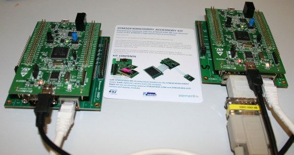
We think [Karl Lunt] has a point when he says that the STM32 Discovery Boards are cool and inexpensive, yet not hobby friendly. But it’s nothing that a little big of creativity can’t solve. Above are pictured three of the hacks he used to tame the Discovery boards.

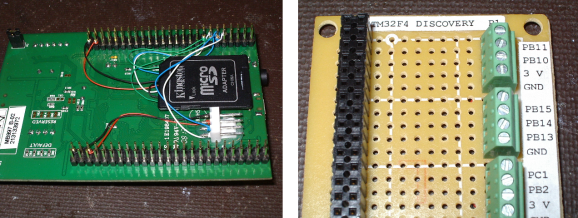
The first is the addition of a microSD card adapter. He soldered wirewrap wire to each of the contacts on the adapter. He recommends a low iron setting to make sure you don’t melt the plastic adapter housing. He then used double stick foam tape to adhere it to the bottom of the dev board. The other ends of the wire are wrapped around the appropriate pins on the dual-row pin header. Similarly, the UART3 connections are broken out from the pin headers to that white quick connect socket. This lets him access serial data without having to solve the USB issues that were vexing him.

Finally, he made his own daughter board to break out the dual row headers into screw terminals. We’ve been hit with problems interfacing hardware with the board’s native connections — jumpering to IDE cables just never worked reliably. This breakout board not only makes it simple, but organizes the pins into groups based on their alternate functions.

Do you remember seeing the hacksaw version of this Discovery board which gives you two dev boards for the price of one?

New STM32 Discovery Board Can Now Be Programmed On Linux

Last Wednesday I posted a video review of the new STM32F0-Discovery board which is built around an ARM Cortex-M0 chip. I speculated that it should work with the open source project aimed at programming these discovery boards. I tested it out and a connection could be made, but no code could be flashed. So I spent a few hours over the weekend and added support.

My updates are already in the stlink repository. After cloning the code, you can use three commands to compile the software (./autogen.sh, ./configure, make). That’s assuming you have all of the necessary dependencies (I had to install libusb-1.0-0-dev) and that you add the udev rule suggested in the documentation (also found in the repository). The program st-util connects to the board and provides a listening port for an ARM debugger (I’m using arm-none-eabi-gdb from CodeSourcery G++ Lite).

When I first started testing, the chip id was reporting as 0. It turns out the register address polled for this information was wrong. After finding that in the almost-900 page reference manual I went through the painstaking process of finding the hex values necessary to properly memory map the device. From there I also updated the blink example to generate an ELF file compatible with the Cortex-M0 chip. So out of the gate you should be able to use an ARM cross compiling toolchain to compile the example, connect to the board with this utility, then use the debugger from the toolchain to connect and flash that example to RAM.

There’s lots more to be done. To fully utilize the chip it is necessary to use a startup file and linker script when compiling. I’ve done nothing in this area, but I hope to work on some tutorials as I get further along. Of course if you have your own successes developing for this board using a Linux machine we want to hear about it!

How To Develop For STM32 Discovery Boards Using Linux

Some hard work has gone into making it possible to develop for the STM32 Discovery board using a Linux system. The board boasts an ARM Cortex-M3 processor, which can be programmed via the mini-USB port on the side. But the company only supports development through their IDE’s which don’t run natively on Linux. The stlink project aims to solve this, providing a toolchain, and making it possible to flash the microcontroller via the USB connection.

The github project linked above also includes a tutorial to get you started (pdf). In addition to a walk through on compiling the software packages, it includes a simple blink program that you can use to test out your hardware. GDB, the familiar open-source debugger, is used to flash the chip. This is a bare-bones tutorial so if you end up posting about your experiences using this toolchain with the Discovery boards we’d love to hear about it.

[Thanks Texane]

Versaloon Ported To STM8 And STM32 Discovery Boards

[Bingo] did some work porting Versaloon for STM8 and STM32 discovery boards. Versaloon is a multiple-architecture programmer that we saw a few weeks back. At its center is an STM32 microprocessor, which greatly simplifies the work necessary to use the two discovery boards instead. Flashing the firmware to the boards will zap the ST-link firmware and [Bingo] doesn’t know of a way to restore that so be warned. This hack is still pretty fresh off the bench, but so far it looks like vsprog and OpenOCD both work just fine with the new hardware.

ARM Prototyping On-the-cheap With STM32 Discovery

STMicroelectronics has another inexpensive development board out; the STM32 Discovery is an ARM Cortex-M3 prototyping platform. Coming in under $10 puts it right along the lines of their 8-bit offering, but this one is 32-bits with 5 KB of RAM and 128 KB of programming memory. It runs a bootloader and has on-board USB for easy programming. They’ve even got a trio of crippled IDE’s to get you started.

Unfortunately this is following a growing trend with the exclusion of Linux support. [Gordon] wrote in to let us know that there is hope in a couple of forms (but not using the USB functionality). The first is a serial programmer using the RS232 that [Paul] came up with (there’s a lot more on his blog so spend some time there). But you can also use the serial debug protocol to program the board.

Either way you’ll still need a method of compiling the code. We’ve had great success rolling our own GNU ARM cross compiler using this guide. Or you can grab a pre-built package by downloading Sourcery G++ lite.

C64 Runs On STM32F429 Discovery

There have been various reincarnations of the Commodore C64 over the years, and [Dave Van Wagner] has created one that can run on an STM32F429ZI Discovery development board. These dev boards have been around quite a few years and feature a 2.4 inch color TFT LCD in addition to the typical I/O circuitry, and are a pretty good value — [Dave] says they currently sell for under $30 through distribution.

The project began earlier this year when [Dave] set out to write a command line program in C# that emulated C64 Basic. He had written a 6502 emulator many years earlier, but had not tested it. [Dave] went on a programming binge in March and got it up and running over a very long weekend. He subsequently decided to add support for VIC-20, TED, and PET as well.

Even though [Dave] says C# is a beautiful language, he subsequently ported the program into C (an ugly language?) in order to run on the Discovery board, swapping the command line terminal interface for real LCD video and a USB keyboard. There’s also an Arduino version (terminal interface only). It runs about 15% slower than a real C64, and there are some limitations still like no SID. But overall, this is a great project and a low-cost way to emulate a C64 in an embedded format. If you want to explore further, here is the Mbed project for the STM32F429, and you can find the Arduino and C# versions on his GitHub page. You may remember [Dave] from the C128 video hack we wrote about last year.

UDP Between STM32-F4 Discovery Boards

stm32-f4-udp

[The Backwoods Engineer] tested out a new accessory kit for the STM32-F4 Discovery board. The image above shows two boards communicating with the UDP protocol. Notice the extra PCB into which each Discovery board has been plugged. This is a third-party add-on which adds Ethernet, RS-232, SD card slot, and a connector for LCD or Camera. We’ve had one of these F4 Discovery boards on hand for a while and haven’t figured out a good way to connect external hardware to the huge dual pin-headers. This doesn’t solve the problem — the base board also includes dual headers to break-out all the pins — but having Ethernet, serial, and SD certainly reduces the need to add all that much more. The other drawback to the hardware is that the sample firmware is targeted at the IAR Embedded Workbench which is neither free, nor in the realm of affordable for hobbyists.

The NIC used on the baseboard has auto-crossover capabilities so the boards were connected using a regular Cat6 patch cable. This example has the boards constantly sending UDP packets with the module on the right reporting status information to a terminal via the serial connection.