Hackaday editors Elliot Williams and Al Williams met up to trade their favorite posts of the week. Tune in and see if your favorites made the list. From crazy intricate automata to surprising problems in Peltier cooler designs, there’s a little bit of everything.
Should bikes have chains? What’s the hardest thing about Star Trek computers to duplicate? Can you make a TV station from a single microcontroller? The podcast this week answers these questions and more. Plus, weigh in on the What’s That Sound contest and you might just score a Hackaday Podcast T-shirt.
For the Can’t Miss segment, Elliot had airships on his mind, while Al’s sick of passwords. But is he sick enough to take electronic pills that transmit his password?
You see it all the time in science fiction: the heroes find old data, read it, and learn how to save the day. But how realistic is that? Forget aliens. Could you read a stack of punch cards or a 9-track tape right now? Probably not, and those are just a handful of decades in the past. Fast forward a few centuries, and punch cards will decay, and tapes will lose their coating. More modern storage is just as bad. It simply isn’t made to last for thousands of years. Microsoft has Project Silica, which aims to store data in quartz glass with a potential lifetime of many thousands of years.
As you might expect, this is a write-once technology. Lasers write the data, and polarization-sensitive microscopes read it back. Electromagnetic fields don’t matter. You can’t accidentally change the data while reading. A square glass platter the size of a DVD can hold about 7 TB of data.
While the program is not a new one, they’ve recently published results using ordinary borosilicate glass (like your Pyrex baking dish is made from) as a storage medium. They say writing is also more efficient, and reading now requires only one camera instead of the three in the original system. The paper identifies birefringent voxel writing, phase voxels, and more.
Obviously, this isn’t for the casual project. But we have to wonder if hackers could do something similar with lower densities, for example. Unlike other methods we’ve seen, no DNA is involved.
An auspicious anniversary passed for me this week, as it’s a decade since I started writing for Hackaday. In that time this job has taken me all over Europe, it’s shown me the very best and most awesome things our community has to offer, and I hope that you have enjoyed my attempts to share all of that with you. It’s worth a moment to reflect on the last ten years in terms of what has made our world during that time. Continue reading “Reflections On Ten Years With The Wrencher”→
Although not as reviled as the sound of nails on chalkboard, the sound of adhesive tape being peeled is quite probably at least as distinctive. With every millimeter of the tape’s removal from the roll sounding like it’s screaming in protest, it has led some to wonder just why this process is noisy enough to be heard from across an open-plan office. Recently [Er Qiang Li] et al. had their paper on a likely theory published in Physical Review E, in which they examine the supersonic air pulses at the core of this phenomenon.
The shockwaves produced by peeling tape, captured on Schlieren imaging. (Credit: Er Qiang Li et al., 2026)
Using rolls of adhesive tape and two microphones synchronized with two high-speed cameras in a Schlieren imaging setup, they gathered experimental data of this stick-slip mechanism. Incidentally, in addition to this auditory effect, adhesive tape is also known for the triboluminescence effect, as well as the generating of X-rays, making them quite the source of scientific demonstrations, even when they’re not also being used to create graphene with.
What they deduced from the recorded data was that the transverse fractures that suddenly appear after the extended stick phase hold a vacuum until they reach the end of the fracture during the brief slip phase, at which point the vacuum collapses very suddenly. This produces a pressure of 9600 Pa and clearly visible shock fronts on the Schlieren images.
Now that we know why peeling adhesive tape from its roll is so noisy, it won’t make it any more quiet, but at least we can add another fascinating science fact to its roll of achievements.
The modern web browser is now far more than a thing for rendering web pages, it’s a multi-faceted environment that can provide a home for almost any application you could imagine. But why should JavaScript or Wasm have all the fun? CSS is Turing complete now, right? Why not, as [Lyra Rebane] has done, write an 8086 emulator in pure CSS?
The web page at the link above may contain an 8086, but missing MMU aside, don’t expect it to run Linux just yet. Instead it has limited resources, just enough to run a demo program. It needs a Chrome-adjacent browser because it uses some CSS functions not available in for example Firefox, but we’ll forgive it that oddity. Its clock is provided by a small piece of JavaScript not because CSS can’t provide one, but because the JS version is more stable.
On one hand this is of little practical use, but to dismiss it as such is to entirely miss the point. It’s in the fine spirit of experimentation, and we love it. Perhaps a better way to look at it is to see what could be done more efficiently with the same idea. A 1970s CISC microprocessor might not be the best choice, but would for example a minimalist and optimized RISC design be more capable? We’re looking forward to where others take this thread.
It’s not the first unexpected computing environment we’ve found, who could forget the DOOM calculator!
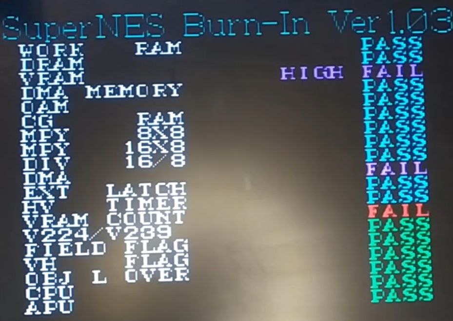
Not what you want to see when testing that ‘repaired’ SNES. (Credit: Skawo, YouTube)
The good part about older game consoles like the Super Nintendo is that they have rather rudimentary region locks, but unfortunately this also gives some people the idea that installing something like the SuperCIC mod chip to make a SNES region-free is easy. The patient that arrived on [Skawo]’s surgery table was one such victim, with the patient requiring immediate surgery to remove the botched installation before assessing the damage.
Here the good news was that the patient features the revision B CPU, making it a good console to rescue. The bad news was that the pads of the old CIC chip had been ripped up, there was a solder bridge on S-PPU1 between two pins and both the installed wiring and soldering were atrocious, requiring plenty of touch-ups.
With the CIC pads already a loss, finishing the SuperCIC mod seemed like a good plan, also since this would make for a nice region-free console. This mod involves a PIC16F630 with special firmware that works with the corresponding CIC IC in each cartridge, while also switching between 50/60 Hz mode to fit the cartridge’s region. After an initial test with PAL and NTSC cartridges everything seemed all right. Then [Skawo] ran the SuperNES Burn-In test from its cartridge, which gave dire news.
2000 m above ground level (AGL), winds are stronger and much, much more consistent than they are at surface. Even if the Earth were a perfect sphere, there’d be a sluggish boundry layer at the surface, but since it’s got all these interesting bumps and bits and bobs, it’s not just sluggish but horribly turbulent, too. Getting above that, as much as possible, is why wind turbines are on big towers. Rather than build really big tower, Beijing Lanyi Yunchuan Energy Technology Co. has gone for a more ambitious approach: an aerostat to take power from the steady winds found at high altitude. Ambitiously called the Stratosphere Airborne Wind Energy System (SAWES), the megawatt-scale prototype has recently begun feeding into the grid in Yibin, Sichuan Province.
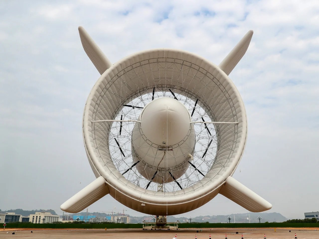
The name might be a bit ambitious, since its 2000 m test flight is only one tenth of the way to the stratosphere, but Yibin isn’t a bad choice for testing: as it is well inland, the S2000 prototype won’t have to contend with typhoons or other ocean storms. The prototype is arguably as ambitious as the name: its 12 flying turbines have a peak capacity of three megawatts. True, there are larger turbines in wind farms right now, but at 60 m in length and 40 m in diameter, the S2000 has a lot of room to grow before hitting any kind of limit or even record for aerostats. We’re particularly interested in the double-hull construction– it would seem the ring of the outer gas bag would do a good job funneling and accelerating air into those turbines, but we’d love to see some wind tunnel testing or even CFD renderings of what’s going on in there.
A rear view shows the 12 turbines inside the double hull. It should guide air into the gap, but we wonder how much turbulence the trusses in there are making.
During its first test flight in January 2026, the system generated generated 385 kilowatt-hours of electricity over the course of 30 minutes. That means it averaged about 25% capacity for the test, which is a good safe start. Doubtless the engineers have a full suite of test flights planned to demonstrate the endurance and power production capabilities of this prototype. Longer flights at higher capacity may have already happened by the time you read this.
Flying wind turbines isn’t a new idea by any means; a few years ago we featured this homemade kite generator, and the pros have been in on it too. Using helium instead represents an interesting design choice–on the plus side, its probably easier to control, and obviously allowing large structures, but the downside is the added cost of the gas. It will be interesting to see how it develops.