There seem to be two schools of thought when it comes to picking an enclosure for your cyberdeck project: you either repurpose the carcass of some commercially produced gadget, or you build a new case yourself. The former can lead to some very impressive results, especially if your donor device is suitably vintage, but the latter is far more flexible as the design will be based on your specific parameters.
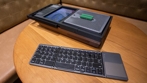
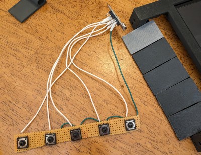
But for the CyberTapeDeck, [Matthew] decided to take a hybrid approach. The final product certainly looks like it’s built into a 1980s portable tape deck, but on closer inspection, you’ll note that the whole thing is actually 3D printed. The replica doesn’t just nail the aesthetics — it also includes the features you’d expect from the real thing, including an extendable handle and functional buttons which the internal Raspberry Pi 3 sees as a macropad thanks to an Arduino Pro Micro.
 A seven inch LCD stands in for the tape door, and while it unfortunately doesn’t look like [Matthew] was able to replicate the opening mechanism to angle the display, you can at least stand the whole thing on its end to provide a more comfortable viewing experience.
[Matthew] says one of the intended purposes for this cyberdeck is to get his son excited about working with electronics and programming, so in a particularly nice touch, he’s mounted a terminal block over the “speaker” that ties into the Pi’s GPIO pins. This provides a convenient interface for experimenting on the go, without getting tangled up in exposed wiring.
We appreciate that [Matthew] has released the STL files for all of the printed parts, because even though it makes a great cyberdeck, the design is begging to house a faux-retro media player.

