In Dune, the Fremen people of Arrakis practice an odd future hybrid religion called “zensunni.” This adds an extra layer of meaning to the title of [Mark Rehorst]’s Arrakis 3.0 sand table, given that the inspiration for the robotic sand table seems to be Zen gardens from Japan.
The dunes on the tabletop version of Arrakis owe nothing to sand worms, but are instead created a rolling metal ball. With all workings happening below, it looks quite magical to the uninitiated, but of course it’s not magic: it’s magnets. Just beneath the tabletop and its sands, the steel ball is being dragged along by the magnetic field of a powerful neodynium magnet.
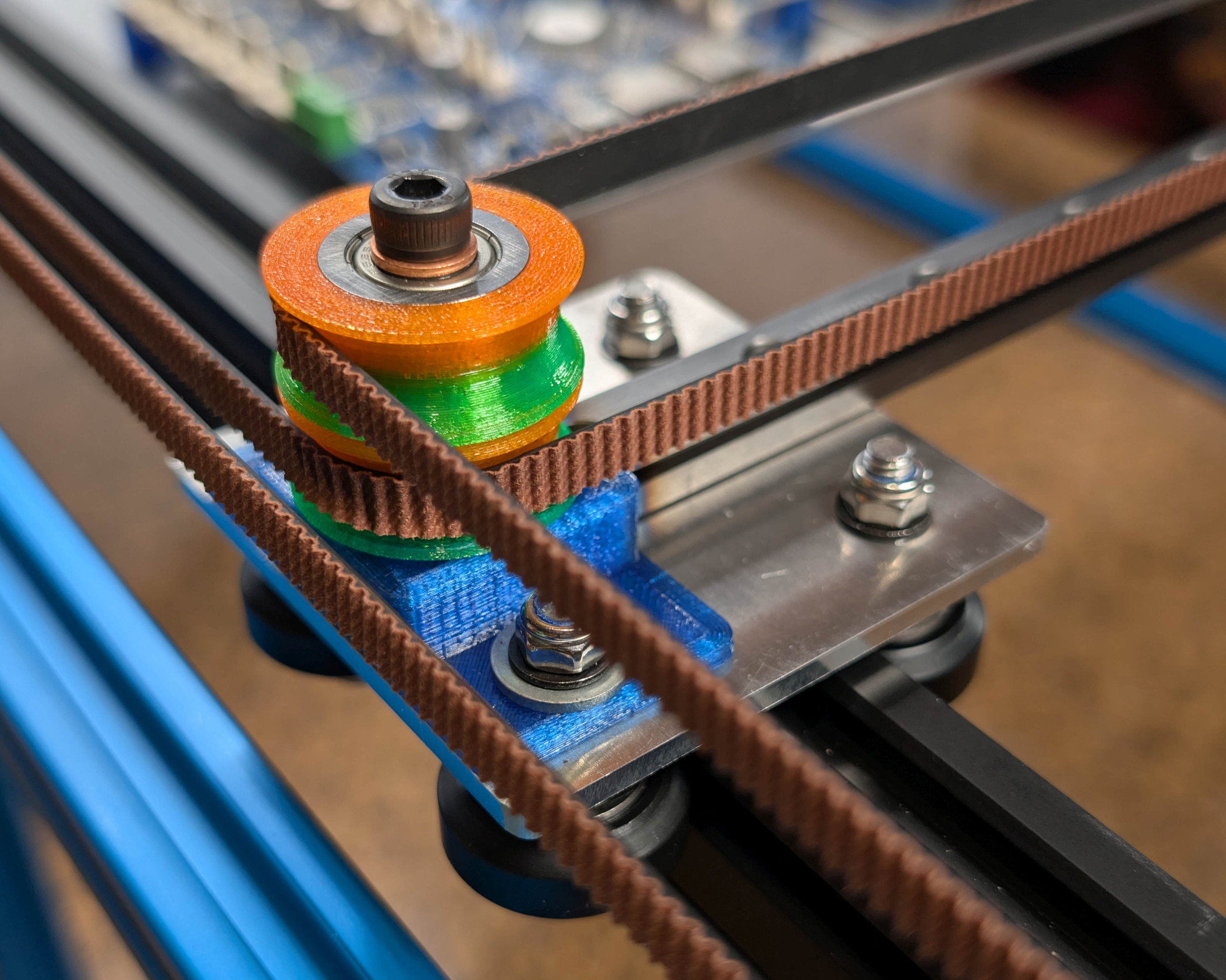 That magnet is mounted in a CoreXY motion system that owes more than a little bit to modern 3D printers. Aside from the geometry, it’s using the standard G6 belt we see so often, along with a Duet3D mainboard, NEMA 17 steppers, and many 3D printed parts to hold its aluminum extrusions together. Thanks to that printer-inspired motion system, the ball can whirl around at 2000 mm/s, though [Mark] prefers to run slower: the demo video below shows operation at 1000 mm/s before the sand has been added.
This build was designed for ease of construction and movement: sized at 2’x4′ (about 61 cm x 122 cm), it fits through doors and fits an off-the-shelf slab of coffee table glass, something that [Mark] wishes he’d considered when building version two. That’s the nice thing about jumping in on a project someone’s been iterating for a while: you’ve got the benefit of learning from their mistakes. You can see the roots of this design, and what has changed, from the one he showed us in 2020.
Naturally you’re not limited to CoreXY for a sand table, though it is increasingly popular — we’ve seen examples with polar mechanisms and even a SCARA arm.
Continue reading “The Zen Must Flow From Arrakis Sand Table”