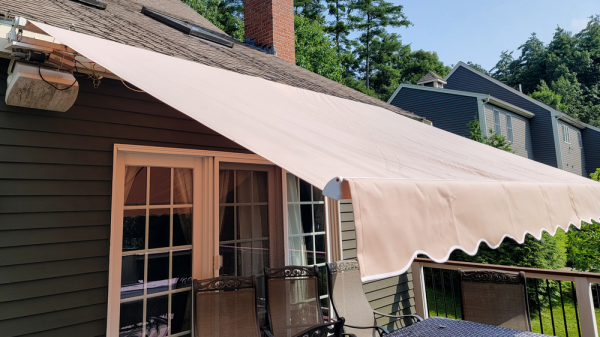
A collage of three images. On top is the main PCB of the headphones, with a charger IC and the main MCU. On the bottom left, it shows ACOK and EN signals going to pullup resistors near the MCU. On bottom right, it shows the charger chip with its pinout overlaying it, highlighting the pads to be probed and later cut.

One Hacker’s Battle To Slightly Improve A Sadistic Sony Headset

One thing you won’t read in reviews of pricey Sony WH-1000XM3 headphones – if you choose them, you’re going to find yourself in a one-sided abusive relationship. A button press or low-battery notification makes the headphones scream at you, ignoring the actual sound volume of what you’re currently listening to. Once they’re discharged, they suddenly emit loud noises, lecture you about how the battery is low, then shut down. Oh, and you can’t use them as they’re charging – if your voicecall lasts longer than expected, you might find yourself being shouted at and forced to fumble around with wires, silently pleading for call participants to wait while you change over to a different headset.

On-PCB footprint for the IC, with two pads carefully cut in half as mentioned in the article[MisterHW] decided to dig in and figure out how to work around at least some of the shortcomings. Naturally, the “no charge while using” limit looked like low-hanging fruit, and a hefty usability improvement too – plus, he suspected the charge cutoff to be masking noise issues already abundant on these headphones. Some painful disassembly later, he was inspecting the charger IC , the MP2625, responsible for power management. Its signals were connected to the MCU using via-in-pad – and some pads had to be cut in half to disconnect the vias.

However, the laborious pad cutting and subsequent careful soldering didn’t turn out to be fruitful. Even with external control of the output inhibition pins, the shutoff still continued – something affected the circuit, whether it was VBUS detection, some other unnoticed via-connected pins on the charger, or sensing on D+/D-. About to run out of life force for this mod, [MisterHW] added a Qi charging circuit, powering a TP4056 wired in parallel with the MP2625. The mod, dubbed HW-1000XM3, made these headphones all that more reliable and less annoying – charger and MCU none the wiser.

Now, all that’s needed to charge these headphones is to slap a magnetic charger coil onto them, and it doesn’t interfere with voicecalls as much as the screaming and forced shutoffs do. Hopefully, Sony eventually learns to test their headphones by having humans use them – it’s far from the only gripes with this lineup, after all. We also hope that the voice notifications will be conquered eventually – this summer, we’ve seen a hacker firmware mod a Bluetooth speaker to make the sounds more pleasant. If your headphones are based on a relatively popular module, repurposing them might be even easier than that!

A DIY self-balancing robot

3D-Printed Self-Balancing Robot Brings Control Theory To Life

Stabilizing an inverted pendulum is a classic problem in control theory, and if you’ve ever taken a control systems class you might remember seeing pages full of differential equations and bode diagrams just to describe its basic operation. Although this might make such a system seem terribly complicated, actually implementing all of that theory doesn’t have to be difficult at all, as [Limenitis Reducta] demonstrates in his latest project. All you need is a 3D printer, some basic electronic skills and knowledge of Python.

The components needed are a body, two wheels, motors to drive those wheels and some electronics. [Limenitis] demonstrates the design process in the video below (in Turkish, with English subtitles available) in which he draws the entire system in Fusion 360 and then proceeds to manufacture it. The body and wheels are 3D-printed, with rubber bands providing some traction to the wheels which would otherwise have difficulty on slippery surfaces.

A PCB driving two stepper motors
The PCB has just a few components, with most of the complexity handled by plug-in modules.

Two stepper motors drive the wheels, controlled by a DRV8825 motor driver, while an MPU-9250 accelerometer and gyroscope unit measures the angle and acceleration of the system. The loop is closed by a Raspberry Pi Pico that implements a PID controller: another control theory classic, in which the proportional, integral and derivative parameters are tuned to adapt the control loop to the physical system in question. External inputs can be provided through a Bluetooth connection, which makes it possible to control the robot from a PC or smartphone and guide it around your living room.

All design files and software are available on [Limenitis]’s GitHub page, and make for an excellent starting point if you want to put some of that control theory into practice. Self-balancing robots are a favourite among robotics hackers, so there’s no shortage of examples if you need some more inspiration before making your own: you can build them from off-the-shelf parts, from bits of wood, or even from a solderless breadboard.

Continue reading “3D-Printed Self-Balancing Robot Brings Control Theory To Life”

Teensy Twofer Of Plug-In Emulated Retro CPUs

[Ted Fried] wrote in with not one but two (2!) new drop-in replacements for widespread old-school CPUs: the Zilog Z80 and the Intel 8088. Both of the “chips” run in cycle-accurate mode as well as in a super turbo mode, which can run so fast that you’ll need to use the Teensy’s internal RAM just to keep up.

Both of these designs have a hardware and software component. The PCBs basically adapt the pinout of the Teensy to the target CPU, with a bunch of 74VLC latches on board to do the voltage level conversion. The rest is a matter of emulating all of the instructions on the Teensy, which is more than fast enough to keep up. If this sounds familiar to you, it’s basically the same approach that [Ted] used last year to bring us his replacement for the 6502 found in the Apple ][ and Commodore 64.

Why would you want an emulated CPU when the originals are still available? [Ted] inherited a busted Osborne I, an ancient Z80 luggable. By replacing the original Z80 with his emulation, he could diagnose the entire system, which led him to discover some bad DRAM chips and get the old beast running again. Or maybe you just want to play IBM XT games at insane speeds?

And it looks like [Ted] has updated his 6502 emulation to include the undocumented C64 opcodes, so if you’re into that scene, you should be covered as well.

If any of this tickles your fancy, head over to [Ted]’s blog, microcore labs, and follow along. Although now that he’s covered most of the famous retrocomputers, we have to ask ourselves what processor is going to be next?

Tube Audio Amplifiers Needn’t Be Complex

There’s a mystique in audiophile circles about tube amplifiers. They can have a very nice sound which is attributed to their even-harmonic distortion, but they are often portrayed as requiring rare and expensive components. You don’t need matched gold-plated tubes and special transformers wound by Japanese monks with oxygen-free silver wire when the tube you’d have found in a TV back in the day paired with a repurposed mains transformer will do. [Mikremk] demonstrates this with a simple but effective amplifier using a PCL82 triode-pentode.

It’s a conventional tube amplifier circuit in which the triode is a preamplifier for the pentode power output stage. The pentode is running in class A mode, and the high impedance of its output is brought down to speaker impedance with that mains transformer. Best of all it doesn’t need a particularly high voltage, with the 40 V DC power coming from a DC-to-DC converter module.

These amplifiers could be found back in the day in some form in most consumer electronics, and remain a spectacularly cheap way to boast a tube amp in your hi-fi even if it might not always be the best possible amp.

Connecting Commercial 433 MHz Sensors To MQTT And Home Assistant With RTL-SDR

When [Elixir of Progress] was looking at setting up environmental sensors around their home to keep track of temperature, humidity and such, the obvious ideas of using WiFi-connected sensors didn’t work due to lack of WiFi range. Although Zigbee (Z-wave) sensors have longer range than WiFi, they are decidedly more expensive, proprietary and require a special transceiver hub. That’s where 433 MHz sensors for weather stations come into the picture.

The idea is simple: virtually all of those sensors – many of them rated for outdoor use – use the unlicensed 433 MHz spectrum that can easily be captured using cheap RTL-SDR (software defined radio) USB dongles. With the data stream from these sensors captured, the open source rtl_433 project enables automatic decoding of these data streams for a wide range of supported sensors.

While Realtek RTL2832-based and other RTL-SDRs can be found for quite cheap, it should be noted that these can run quite hot. Rather than heatsinking the IC, for this project it was elected to only listen sporadically and allow the RTL-SDR receiver to cool down in between listening sessions.

Getting the data from there into Home Assistant, InfluxDB or similar is easy, as rtl_433 can output the decoded data directly to an Influx database, MQTT broker as well as other formats. In this case, the data was sent via MQTT with the Home Assistant instance configured to treat these MQTT topics as sensors. With each sensor’s location carefully registered, this allows for setting up a dense, very low-power network of 433 MHz sensors for monitoring and home automation purposes.

Turning A Microchip MPLAB Snap Into A UDPI AVR Programmer

The Unified Program and Debug Interface (UPDI) is Microchip’s proprietary interface for programming and on-chip debugging, and has become the standard on AVR MCUs after Microchip’s purchase of Atmel. Being a proprietary interface means that even entry-level programmers like the Atmel-ICE are rather expensive at over $100. That’s when for [Scott W Harden] the question arose of whether the much cheaper MPLAB Snap board (~$34) could be used as well for AVR UDPI purposes.

The stages of grief that [Scott] went through before he had it working involved among others the updating of the MPLAB Snap board firmware, getting yelled at by the Microchip Studio IDE when attempting to use the Snap for AVR MCU programming, and ultimately fixing the board following the relevant Microchip Engineering Technical Note (ETN #36) that specifies the removal of a 4.7 kΩ pull-down resistor (R48) on the Snap board. This allows the UDPI line to be pulled high by the MCU.

As the ETN notes, an external pull-up may also be used to override the pull-down, which would leave the ICSP functionality of of the Snap intact. As [Scott] mentions in his conclusion, it feels as if UDPI AVR support with the Snap is really an afterthought for Microchip. Meanwhile there are also more DIY solutions as [Scott] adds, which are useful for just flashing the MCU. An example is with a USB-TTL serial adapter and pymcuprog.

The problem with DIY solutions like jtag2updi, ftdi2updi, and their kin is the effort required to assemble them, and the uncertainty of long-term support as the UPDI ecosystem keeps evolving with new devices and new features. The MPLAB Snap with resistor mod may be just that middle ground between an Atmel-ICE and reverse-engineered OSS projects.

(Featured image: MPLAB Snap resistor mod illustrated, from Microchip ETN #36)

A beige keyboard with blue and grey keys sits on a colorful deskmat atop a wooden desk. A small box with a round Touch ID button sits next to the keyboard.

Standalone Touch ID For Your Desktop Mac

With the proliferation of biometric access to mobile devices, entering a password on your desktop can feel so passé. [Snazzy Labs] decided to fix this problem for his Mac by liberating the Touch ID from a new Apple keyboard.

When Apple introduced its own silicon for its desktops, it also revealed desktop keyboards that included their Touch ID fingerprint reader system. Fingerprint access to your computer is handy, but not everyone is a fan of the typing experience on Apple keyboards. Wanting to avoid taping a keyboard under his desk, [Snazzy Labs] pulled the logic board from the keyboard and designed a new 3D printed enclosure for the Touch ID button and logic board so that the fingerprint reader could reside close to where the users hands actually are.

One interesting detail discovered was the significantly different logic boards between the standard and numpad-containing variants. The final enclosure designs feature both wireless and wired versions for both the standard and numpad logic boards if you should choose to build one of your own. We’re interested to see if someone can take this the next step and use the logic board to wire up a custom mechanical keyboard with Touch ID.

If [Snazzy Labs] seems familiar, you may recognize him from their Mac Mini Mini. If you’re more in the mood to take your security to the extreme, check out this Four Factor Biometric Lockbox that includes its own fingerprint reader.

Continue reading “Standalone Touch ID For Your Desktop Mac”