Celebrate Display Diversity For A Circuit Circus Clock

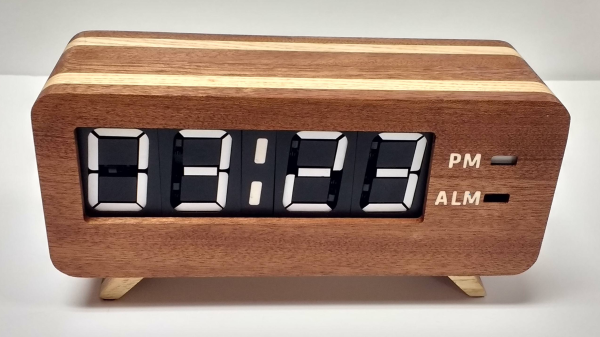
There’s a lot to be said for nice, tidy projects where everything lines up and looks pretty. Seeing straight lines and pleasing proportions speaks to our obsessive-compulsive tendencies, and tends to soothe the mind and calm the spirit. But disorder is not without its charm, and mixing it up a little from time to time, such as with this mixed-media digital clock, can be a good idea.

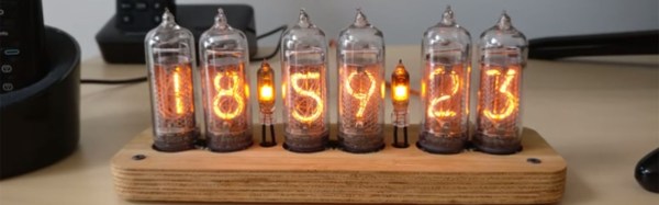
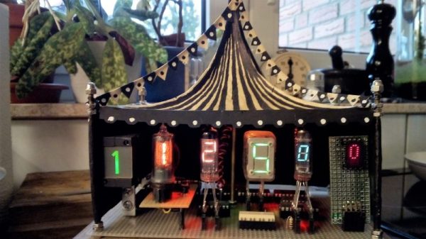
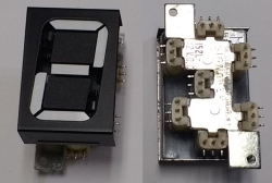
Now, we know what you’re thinking — yet another Nixie clock. True, but that’s only half the story — or more accurately, one-sixth. There’s but a single Nixie in [Fuselage]’s circus-punk themed clock, used for the least significant digit in the hours part of the display. The other digits are displayed with four seven-segment devices — a Numitron, a vacuum fluorescent display, and an LED dot display — plus a real oddball, an old electromechanical display with individual slides for each character and a rear-screen projector. The RTC part of the project is standard Arduino fare, but as you can imagine the power supply needed for such a diversity of displays is pretty complex and has to provide everything from +5 to -270 volts. Each display needs its own driver, too, making this more of a zoo than a circus. The mixed up look just works with the circus theme, too. We’d really like more information on the projector display, though.

Looking for a real statement for your next clock build? Check out the rare as hens’ teeth NIMO tube.

Continue reading “Celebrate Display Diversity For A Circuit Circus Clock”

Seven-Segment Flip Clock Display Finally Finished

Earlier this year, we mentioned in a Hackaday Links article that [Spencer Hamblin] was in the process of building a seven-segment flip clock. Well, it’s finally finished, and it looks great!

Vintage seven segment digits make up the display. These digits work the same way that flip-dot displays work – current through each segment’s coil creates a magnetic field which causes the segment to flip over. Current in the other direction creates the opposite magnetic field and flips the segment the other way. On these digits, there are three connections on the coils. The middle one is power and the other two are used to enable and disable the segment – ie., flip it one way or the other. To save on pins on the microcontroller, [Spencer] connected all the middle coil pins together on a digit. Each coil can be powered using a single pin on the microcontroller. Similarly, the segments for each digit are connected together as well, so one pin on the micro controls the same segment on each of the digits. The microcontroller in question is the AVR ATMega48.

There are two parts of the clock face left to do: AM/PM and whether the alarm is set or not. [Spencer] used a fifth digit, slightly offset, for those – the top and middle segments are used.

For the housing of the clock, [Spencer] used layers of offsetting colored wood. The wood (sapele and ash) were CNC cut and aligned. The back plate, also made from wood, holds buttons for setting the time and alarm, as well as some LEDs for what [Spencer] calls the “daylight alarm.” A capacitive sensor on the top of the unit (inside the wooden case) is used to turn the alarm off.

The result, after sanding and shellacing, looks amazing. [Spencer] nailed the art-deco look he was going for. There are plenty of pictures and the circuit designs, schematics and code are on [Spencer]’s Hackaday.io page, and you can find the Hackaday links post here. This is a complete log of a project we mentioned earlier on Hackaday, here, but there are other mechanical flip display clock projects, such as this DIY mechanical flip seven-segment prototype, or, you could create your own (really big) clock using this Lego mechanical seven-segment display.

via Reddit.

Modernizing A 170 Year Old Antique Grandfather Clock

Frankly, we let out a yelp of despair when we read this in the tip line “Antique Grandfather clock with Arduino insides“! But before you too roll your eyes, groan, or post snark, do check out [David Henshaw]’s amazing blog post on how he spent almost eight months working on the conversion.

Before you jump to any conclusions about his credentials, we must point out that [David] is an ace hacker who has been building electronic clocks for a long time. In this project, he takes the antique grandfather clock from 1847, and puts inside it a new movement built from Meccano pieces, stepper motors, hall sensors, LEDs, an Arduino and lots of breadboard and jumper wires while making sure that it still looks and sounds as close to the original as possible.

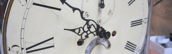
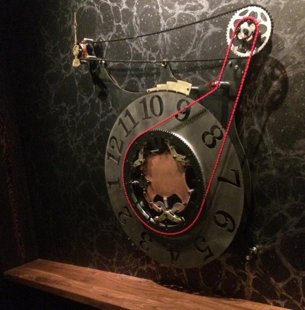
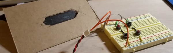
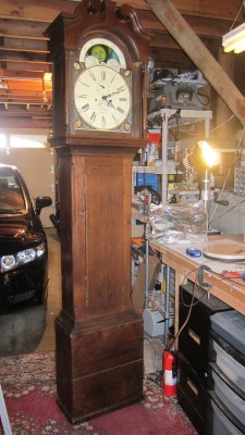
He starts off by building a custom electro-mechanical clock movement, and since he’s planning as he progresses, meccano, breadboard and jumper wires were the way to go. Hot glue helps preserve sanity by keeping all the jumper wires in place. To interface with all of the peripherals in the clock, he decided to use a bank of shift registers driven from a regular Arduino Uno. The more expensive DS3231 RTC module ensures better accuracy compared to the cheaper DS1307 or similar clones. A bank of RGB LEDs acts as an annunciator panel inside the clock to help provide various status indications. The mechanical movement itself went through several iterations to get the time display working with a smooth movement of the hands. Besides displaying time, [David] also added a moon phase indicator dial. A five-rod chime is struck using a stepper motor driven cam and a separate solenoid is used to pull and release three chime hammers simultaneously to generate the loud gong sounds.

And here’s the amazing part – he did all of this before laying his hands on the actual grandfather clock – which was shipped to him in California from an antique clock specialist in England and took two months to arrive. [David] ordered just the clock housing, dial/face and external parts, with none of the original inner mechanism. Once he received it, his custom clock-work assembly needed some more tweaking to get all the positions right for the various hands and dials. A clock like this without its typical “ticktock” sound would be pretty lame, so [David] used a pair of solenoids to provide the sound effect, with each one being turned on for a different duration to produce the characteristic ticktock.

At the end of eight months, the result – christened Judge – was pretty satisfying. Check the video below to judge the Judge for yourself. If you would like to see some more of [David]’s clockwork, check out Dottie the Flip Dot Clock and A Reel to Reel Clock.

Continue reading “Modernizing A 170 Year Old Antique Grandfather Clock”

Slimline Nixie Clocks

Everyone needs to build a Nixie clock at some point. It’s a fantastic learning opportunity; not only do you get to play around with high voltages and tooobs, but there’s also the joy of sourcing obsolete components and figuring out the mechanical side of electronic design as well. [wouterdevinck] recently took up the challenge of building a Nixie clock. Instead of building a clock with a huge base, garish RGB LEDs, and other unnecessary accouterments, [wouter] is building a minimalist clock. It’s slimline, and a work of art.

The circuit for this Nixie clock is more or less what you would expect for a neon display project designed in the last few years. The microcontroller is an ATMega328, with a Maxim DS3231 real time clock providing the time. The tubes are standard Russian IN-14 Nixies with two IN-3 neon bulbs for the colons. The drivers are two HV5622 high voltage shift registers, and the power supply is a standard, off-the-shelf DC to DC module that converts 5 V from a USB connector into the 170 V DC the tubes require.

The trick here is the design. The electronics for this clock were designed to fit in a thin base crafted out of sheets of bamboo plywood. The base is a stackup of three 3.2mm thick sheets of plywood and a single 1.6 mm piece that is machined on a small desktop CNC.

Discounting the wristwatch, this is one of the thinnest Nixie clocks we’ve ever seen and looks absolutely fantastic. You can check out the video of the clock in action below, or peruse the circuit design and code for the clock here.

Continue reading “Slimline Nixie Clocks”

Steampunk-Inspired Art Clock!

Getting paid to do what you enjoy is a special treat. A machinist and fabricator by trade — hobbyist hacker by design — [spdltd] was commissioned to build a mechanical art installation with a steampunk twist. Having complete creative control, he convinced his client to let him make something useful: a giant electro-mechanical clock.

Pieced together from copper, brass, steel, aluminium, and stainless steel, this outlandish design uses an Arduino Yun — a combination Linux and Arduino microcontroller board — to control the stepper motor and query the internet for the local time. Upon boot, the clock auto-calibrates by rotating the clock face until a sensor detects an extra peg and uses that to zero on twelve o’clock; the Yun then grabs the local time over the WiFi and sends the stepper motor a-spinning ’till the correct time is displayed.

At first glance, you may find it hard to get an accurate read of what time it is, but an accent piece’s pegs denote the quarter hour once it lines up with the notch above each hour. At least this one doesn’t require you to match colours or do much math to check the time.

Continue reading “Steampunk-Inspired Art Clock!”

Mechanical Image Acquisition With A Nipkow Disc

If you mis-spent your teenage years fishing broken televisions from dumpsters and either robbing them for parts or fixing them for the ability to watch The A Team upstairs rather than in the living room as I did, then it’s possible that you too will have developed a keen interest in analogue television technology. You’ll know your front porch from your blanking interval and your colour burst, you might say.

An illustration of a simple Nipkow disk. Hzeller (CC BY-SA 3.0).

There was one piece of television technology that evaded a 1980s dumpster-diver, no 625-line PAL set from the 1970s was ever going to come close to the fascination of the earliest TV sets. Because instead of a CRT and its associated electronics, they featured a spinning disk with a spiral pattern of holes. These mechanical TV systems were quickly superseded in the 1930s by all-electronic systems, so of the very few sets manufactured only a fraction have survived the intervening decades.

The spinning disk in a mechanical TV is referred to as a Nipkow disk, after its inventor, [Paul Gottlieb Nipkow]. [Nipkow] conceived and patented the idea of a spinning disk with a spiral of holes to dissect an image sequentially into a series of lines in the 1880s, but without the benefit of the electronic amplification that would come a few decades later was unable to produce a viable system to demonstrate it. It would be in the 1920s before [John Logie Baird] would develop the first working television system using [Nipkow]’s invention.

Continue reading “Mechanical Image Acquisition With A Nipkow Disc”

Towards DIY Flip Digit Clocks

Seven segment displays and Nixies are one thing, but the king of all antique display technologies must be electromechanical flip dots. These displays, usually found in train stations or rarely on old bus lines, are an array of physical disks, black on one side, light on the other, that ‘flip’ back and forth with the help of an electromagnet. They’re expensive and impressive, driving them is a pain, but oh man do they look awesome.

While flip dot displays can be bought new if you know where to look, [sjm4306] had the idea to build his own out of inexpensive materials. It might just be a prototype, but we’re saying he’s succeeded. He has the workings of a seven flip-segment display, and the techniques he’s using mean it shouldn’t be too expensive to build your own.

Instead of building a matrix of flip dots, [sjm] is building a mechanical seven-segment display. Each of the segments are 3D printed in black PLA, and mounted to a piece of cardboard via a thin wire ‘axel’ going through the length of the segment. Where normal flip dots use an electromagnet to change each dot from one state to another, [sjm] mounted a very small vibrating pager motor to one end of the segment. When one half of a tact switch h-bridge is activated, the segment flips to the front. When the other half of the h-bridge is activated, the segment flips back.

Right now, this hardware is in the ‘extreme prototype’ stage, but results so far are encouraging. [sjm] has already designed a single-segment ‘module’. Plans for the electronics include optocouplers for two microcontroller pins for each segment and reed relays for each individual digit. For a four-digit display, these flip digits will only require 18 I/O pins.

You can check out [sjm4306]’s video for this project below. It’s a little bit long, but watch those things flip!

Continue reading “Towards DIY Flip Digit Clocks”