We’ve been contacted by [Cedric], telling us about the smallest ARM MCU he’s ever seen – Huada HC32L110. For those of us into miniature products, this Cortex-M0+ package packs a punch (PDF datasheet), with low-power, high capabilities and rich peripherals packed into an 1.6mm x 1.4mm piece of solderable silicon.
This is matchstick head scale computing, with way more power than we previously could access at such a scale, waiting to be wrangled. Compared to an 8-bit ATTiny20 also available in WLCSP package, this is a notable increase in specs, with a way more powerful CPU, 16 times as much RAM and 8-16 times the flash! Not to mention that it’s $1 a piece in QTY1, which is about what an ATTiny20 goes for. Being a 0.35mm pitch 16-pin BGA, your typical board house might not be quite happy with you, but once you get a board fabbed and delivered from a fab worth their salt, a bit of stenciling and reflow will get you to a devboard in no time.
Drawbacks? No English datasheet or Arduino port, and the 67-page PDF we found doesn’t have some things like register mappings. LILYGO promised that they will start selling the devboards soon, but we’re sure it wouldn’t be hard for us to develop our own. From there, we’d hope for an ESP8266-like effect – missing information pieced together, translated and made accessible, bit by bit.
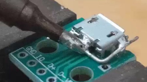
When it comes to soldering such small packages, we highly recommend reflow. However, if you decide to go the magnet wire route, we wouldn’t dare object – just make sure to send us pictures. After all, seems like miniature microcontrollers like ATTiny20 are attractive enough of a proposition that people will pick the craziest route possible just to play with one. They say, the madness of the brave is the wisdom of life.
We thank [Cedric] for sharing this with us!