A Simple Guide To Bit Banged I2C On The 6502

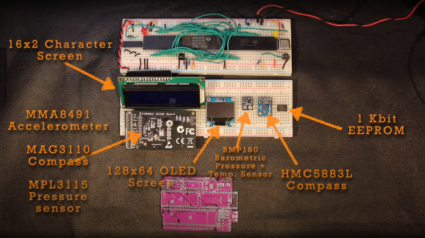
We covered [Anders Nielsen]’s 65duino project a short while ago, and now he’s back with an update video showing some more details of bit-banging I2C using plain old 6502 assembly language.

Obviously, with such a simple system, there is no dedicated I2C interface hardware, so the programmer must take care of all the details of the I2C protocol in software, bit-banging it out to the peripheral and reading back the response one bit at a time.

The first detail to concern us will be the I2C addresses of the devices being connected to the bus and how low-level bit manipulation is used to turn the 7-bit I2C address into the byte being bit-banged. As [Anders] shows, setting a bit is simply a logical-OR operation, and resetting a bit is a simple logical-AND operation using the inversion (or one’s complement) bit to reset to form a bitmask. As many will already know, this process is necessary to code for a read or a write I2C operation. A further detail is that I2C uses an open-collector connection scheme, which means that no device on the bus may drive the bus to logical high; instead, they must release the drive by going to the high impedance state, and an external pull-up resistor will pull the bus high. The 6532 RIOT chip (used for I/O on the 65unio) does not have tristate control but instead uses a data direction register (DDR) to allow a pin to be an input. This will do the job just fine, albeit with slightly odd-looking code, until you know what’s going on.
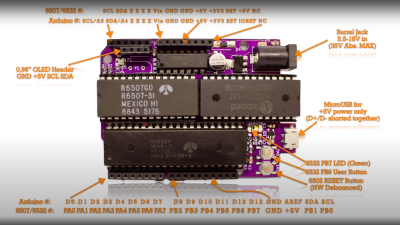
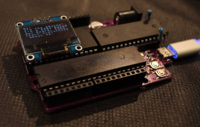
From there, it’s a straightforward matter to write subroutines that generate the I2C start, stop, and NACK conditions that are required to write to the SSD1306-based OLED to get it to do something we can observe. From these basic roots, through higher-level subroutines, a complete OLED library in assembly can be constructed. We shall sit tight and await where [Anders] goes next with this!

We see I2C-connected things all the time, like this neat ATtiny85-based I2C peripheral, and whilst we’re talking about the SSD1306 OLED display controller, here’s a hack that shows just how much you can push your luck with the I2C spec and get some crazy frame rates.

Continue reading “A Simple Guide To Bit Banged I2C On The 6502”

Hackaday Prize 2023: 65uino 6502 Learning In A Familiar Package

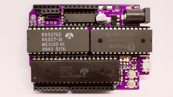
[Anders Nielsen] presents his entry for the 2023 Hackaday Prize: The 65uino. Which as you might be able to guess, is a 6502-based microcomputer wedged into an Arduino Uno form factor (well, almost wedged in, but we’ll let it slide) The premise is simple, older micros are easier to understand, the board can be build up from new-old or salvaged stock, and that’s more chips on boards and less sitting on a dusty shelf. After all, even though the 6502 in its original form is long obsolete, it’s far better to be pushing some electrons around, than sitting there decaying.

The OLED frame buffer is bigger than the host’s entire RAM. No problem!

From an educational perspective, the first lesson is the hand-soldering of through-hole DIP components and a smattering of straightforward surface mount parts in their supporting roles.  Then on to setting up the cc65 toolchain. To say this is a pure 6502 system is a little misleading, it actually uses the 6507 device variant, which is a die-bond variant of the same device but with only 28 of the pins utilized.

The use of the 6532 RIOT (RAM-I/O-Timer) chip provides two 8-bit ports of GPIO as well as a timer and 128 bytes of SRAM, making the design more compact. There is a socket that will accept a 24 or 28-pin E(E)PROM device, with the extra four pins removable and the PCB snapped off if fitment into a standard ‘Uno case is desirable. Neat!

Full hardware build and PCB design (using KiCAD) are available on the 65uino GitHub page. Just remember folks, with everything minimal 6502 related — some assembly required :D

We see the 6502 a lot, let’s be fair. But why not? Here’s a slightly more practical board with a bit more resources, an absolute beast of a luggable dual-6502 machine, and yet another 6502 verilog implementation ready to be dropped into a spare corner of a FPGA project that needs a little extra.

CP/M 6502-Style

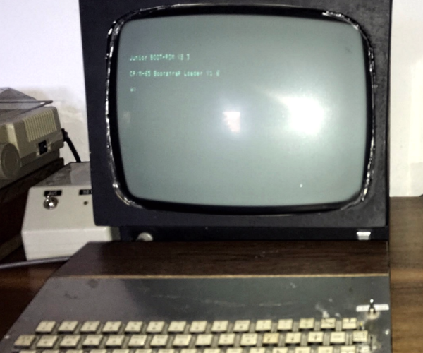
There are projects you create to share with the world, but there are also those you do just because you want something for yourself. Lucky for us, [Dietrich-L]’s 30-year-long project to create CPM-65, a CP/M-like OS for the 6502, has become both.

[Dietrich-L] does admit that the documentation is “sparse” and “for my personal needs.” Still, the OS has most of what you’d expect and runs well on the target system, a heavily-modified Elektor Junior with 57 kB of RAM. The disk structure is compatible with CP/M, although the Transient Program Area (TPA) apparently starts at $200, which is a bit different from a typical CP/M. Apparently, the system uses some low memory which necessitated the relocation. Just in case you were hoping, CPM-65 doesn’t emulate an 8080 system, so you can’t run normal CP/M programs. You just get a similar operating environment and tools.

The 31 commands listed include an assembler, BASIC, Forth, an editor, and some disk tools, along with a debugger. Xmodem is available, too. Everything is written in assembly for the CPM-65 assembler, so bootstrapping could be an issue if you need to make any changes.

Speaking of changes, there is some documentation in the docs sub-directory, including the layout of [Dietrich-L]’s system, which would be handy if you were trying to run this on your own hardware. You’ll also find basic commands for the editor, details of the assembler, and some other documents.

[Dietrich-L] notes that he was unaware when he started the project that there were other similar projects. DOS/65 (which has a port for the Commodore 64), OUP/M (which hasn’t been updated since 1983), and CPM65 (apparently no relation, but very impressive), which appeared in 2022.

If you need a 6502 computer, grab a breadboard, although adding the disk drive is an exercise left to the reader. Or, grab an FPGA but expect more work.

Thanks [Stephen Walters] for the tip!

From A 6502 Breadboard Computer To Lode Runner And Beyond

As disruptive and generally unpleasant as the pandemic lockdowns of 2020 were, they often ended up being a catalyst for significant personal growth. That was often literal growth, thanks to stress eating, but others, such as [Eric Badger], used the time to add skills to his repertoire and build a breadboard 6502 computer and so much more.

For those of you looking for a single endpoint to this story, we’re sorry to disappoint — this isn’t really one of those stories. Rather, it’s a tale of starting as a hardware newbie with a [Ben Eater] 6502 breadboard computer kit, and taking it much, much beyond. Once the breadboard computer kit was assembled, [Eric] was hooked, and found himself relentlessly expanding it. At some point, he decided to get the classic game Lode Runner going on his computer; this led to a couple of iterations of video cards, including a foray away from the breadboards and into PCB design. That led to a 6502 emulator build, and a side quest of a Raspberry Pi Pico Lode Runner appliance. This naturally led [Eric] to dip a toe into the world of 3D printing, because why not?

Honestly, we lost track of the number of new skills [Eric] managed to add to his toolkit in this video, and we’re sure this isn’t even a final accounting — there’s got to be something he missed. It’s great stuff, though, and quite inspirational — there’s no telling where you’ll end up when you start messing around with hardware hacking.

Continue reading “From A 6502 Breadboard Computer To Lode Runner And Beyond”

Squeezing A Minimalist 6502 Retrocomputer Onto A Single Breadboard

Over the years, and especially lately, we’ve seen tons of single-board retrocomputer builds. That’s fine with us — the more, the merrier. But they all start to run together a bit, with little to distinguish between them. Not so this about-as-compact-as-possible 6502 computer that fits on a single breadboard.

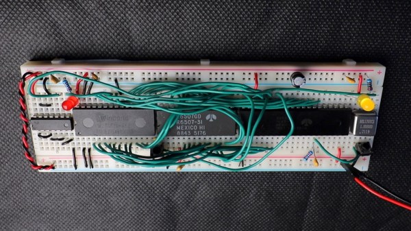
Now, when you do the math, it seems like there’s no way that [Anders Nielsen] would have been able to fit even a minimal chipset onto a standard solderless breadboard. The 40-pin 6502 alone takes up nearly two-thirds of the connections available; add in equally large but necessary chips like the 6522 interface adapter, ROM and RAM chips, and some support ICs, and one breadboard isn’t going to cut it. Luckily, some frugal engineers at MOS back in the 70s came up with the 6507, a variant on the 6502 in a 28-pin DIP. The other key to this build is the 6532 RAM-I/O-timer chip or RIOT, which puts a tiny amount of RAM and some IO lines on a single 40-pin DIP. Along with a 28-pin ROM, a 14-pin hex inverter, and a little crystal oscillator, the entire chipset just barely fits on a single breadboard.

But what can this minimalist 6502 actually do? As you can see in the video below, anything a 555 timer can do, and maybe a little bit more. That’s not a dig, of course — [Anders] actually calls out his initial blinkenlight application as a little more than a glorified 555, and actually comes up with a marginally more complex application just to prove the point. The interesting part here is dealing with the constraints imposed by the limited resources available on this machine.

We’re looking forward to whatever comes next for this clever build. It’s hard to see how some of the plans [Anders] has for it will still fit on a single breadboard, though — these things tend to spread out as they go.

Continue reading “Squeezing A Minimalist 6502 Retrocomputer Onto A Single Breadboard”

Blinky Project Is 6502s All The Way Down

Virtually any platform you might find yourself programming on has some simple method of running a delay. [Joey Shepard] got rather creative on a recent project, though, relying on a rather silly nesting method that we’re calling 6502s All The Way Down.

The project in question was a simple PCB that was shaped like a robot, with blinking LED eyes. Typically, you’d simply reach for the usual sleep() or delay() function to control the blink rate, but [Joey] went off-piste for this one. Instead, the PIC32 on the board runs a 6502 emulator written in MIPS assembly. This emulated 6502 is then charged with running a further 6502 emulator coded in 6502 assembly, and so on, until there’s 6502 emulators running six-deep on the humble microcontroller. The innermost emulator runs a simple program that blinks the LED eyes in a simple loop. With the overhead of running six emulators, though, the eyes only blink at a rate of roughly once every two seconds.

It’s an amusing and complicated way to write a blink program, and we applaud [Joey] for going to all that trouble. We imagine it was a great way to learn about programming the PIC32 as well as emulation in general. Meanwhile, if you’re working on your own emulator feats, be sure to let us know!

A breadboard with a few DIP chips

Minimalist 6502 System Uses A CPU And Not Much Else

A central processing unit, or CPU, is the heart of any computer system. But it’s definitely not the only part: you also need RAM, ROM and at least some peripherals to turn it into a complete system that can actually do something useful. Modern microcontrollers typically have some or all of these functions integrated into a single chip, but classic CPUs don’t: they were meant to be placed on motherboards along with dozens of other chips. That’s why [c0pperdragon]’s latest project, the SingleBreadboardComputer, is such an amazing design: assisting its 6502 CPU are just four companion chips.

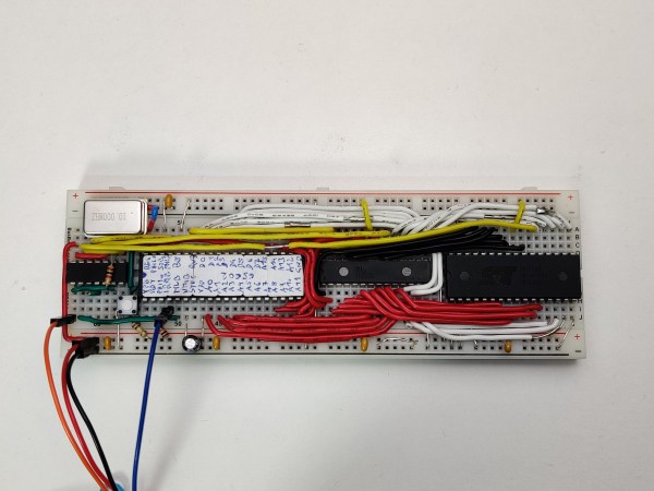
The entire system takes up just one strip of solderless breadboard. Next to the CPU we find 32 KB of SRAM, 32 KB of flash and a clock oscillator. The fifth chip is a 74HC00 quad two-input NAND gate, which is used as a very tiny piece of glue logic to connect everything together. Two of its NAND gates are used for address decoding logic, allowing either the ROM or RAM chip to be selected depending on the state of the CPU’s A15 line as well as blocking the RAM during the low phase of the system clock. The latter function is needed because the address lines are not guaranteed to be stable during the low phase and could cause writes to random memory locations.

The remaining two NAND gates are connected as an RS-flipflop in order to implement a serial output. This is needed because the CPU cannot keep its outputs in the same state for multiple clock cycles, which is required for a serial port. Instead, [c0pperdragon] uses the MLB pin, normally used to implement multiprocessor systems, to generate two-clock pulses, and stores the state in the flipflop for as long as needed. A few well-timed software routines can then be used to transmit and receive serial data without any further hardware.

Currently, the only software for this system is a simple demonstration that sends back data received on its serial port, but if you fancy a challenge you could write programs to do pretty much anything. You could probably find some inspiration in other minimalist 6502 boards, or projects that emulate a complete motherboard in an FPGA.