No Moving Parts: Phased Array Antennas Move While Standing Still

If you watch old science fiction or military movies — or if you were alive back in the 1960s — you probably know the cliche for a radar antenna is a spinning dish. Although the very first radar antennas were made from wire, as radar sets moved higher in frequency, antennas got smaller and rotating them meant you could “look” in different directions. When most people got their TV with an antenna, rotating those were pretty common, too. But these days you don’t see many moving antennas. Why? Because antennas these days move electrically rather than physically using multiple antennas in a phased array. These electronically scanned phased array antennas are the subject of Hunter Scott’s talk at 2018’s Supercon. Didn’t make it? No problem,  you can watch the video below.

While this seems like new technology, it actually dates back to 1905. Karl Braun fed the output of a transmitter to three monopoles set up as a triangle. One antenna had a 90 degree phase shift. The two in-phase antennas caused a stronger signal in one direction, while the out-of-phase antenna canceled most of the signal and the resulting aggregate was a unidirectional beam. By changing the antenna fed with the delay, the beam could rotate in three 120 degree steps.

Today phased arrays are in all sorts of radio equipment from broadcast radio transmitters to WiFi routers and 5G phones. The technique even has uses in optics and acoustics.

Continue reading “No Moving Parts: Phased Array Antennas Move While Standing Still”

The Engineering Of An Ultrasonic Phased Array

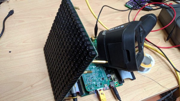
Ultrasonic phased arrays are one of the wonders of the moment, with videos of small items being levitated by them shared far and wide. We’ve all seen them and some of us have even wondered about building them, but what about the practical considerations? Just how would you drive a large array of ultrasonic transducers, and how would you maintain a consistent phase relationship between their outputs? It’s a problem [Niklas Fauth] has been grappling with over the three iterations so far of his ultrasonic phased array project, and you can follow his progress on the latest build.

The arrays themselves are a 16 by 16 grid of cheap ultrasonic transducers on a PCB, fed by HV583 high-voltage shift registers. These chips have proven to be particularly problematic, their drivers having a relatively high internal resistance which leaves them prone to overheating.

An interesting solution to a problem comes from the transducers having a polarity, but because it doesn’t matter in their usual application, that polarity not being marked. He’s overcome this by using the STM32 he has managing power alongside his BeagleBone to listen through a sensor as the ‘Bone supplies each transducer in turn with a known phase. An internal map can then be created, such that the appropriate phase can be applied on a transducer-by-transducer basis.

It’s the fascination with the subject that we find appealing, this is version three and version two worked. Most of us would make one and call it a day. It’s something we’ve seen before from [Niklas], after all this is someone who plays with turbomolecular pumps for fun. Meanwhile if you would like to learn more about ultrasonic arrays and acoustic levitation, it was the subject of one of this year’s Hackaday Belgrade talks.

Visualization Of A Phased Array Antenna System

Phased array antenna systems are at the cusp of ubiquity. We now see Multiple-Input Multiple-Output (MIMO) antenna systems on WiFi routers. Soon phased array weather radar systems will help to predict the weather and keep air travel safe, and phased array base stations will be the backbone of 5G which is the next generation of wireless data communication.  But what is a phased array antenna system?  How do they work?  With the help of 1024 LEDs we’ll show you.

Continue reading “Visualization Of A Phased Array Antenna System”

Steering Sound With Phased Array

entiresystem

[Edward] and [Tom] managed to build an actual phased array speaker system capable of steering sound around a room. Powered by an Atmega 644, this impressive final project uses 12 independently controllable speakers that each have a variable delay. By adjusting the delay at precise intervals, the angle of maximum intensity of the output wave can be shifted, there by “steering” the sound.

Phased arrays are usually associated with EM applications, such as radar. But the same principles can be applied to sound waveforms. The math is a little scary, but we’ll walk you through only what you need to know in case you’re ever in need to steer sound with a speaker and a servo phased array sound system.

Continue reading “Steering Sound With Phased Array”

A Phased-Array Ultrasonic 3D Scanner From Scratch

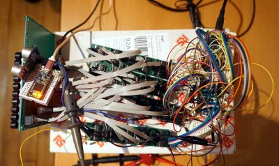
Who wouldn’t want an autonomous drone to deliver cans of fizzy drink fresh from the fridge? [Alex Toussaint] did, and in thinking how such a machine might work he embarked on a path that eventually led him to create a fully functional ultrasonic 3D scanner. In writing it up he’s produced a straightforward description of how the system works, which should also be of interest to anyone curious about phased array radar. He starts with an easy-to-understand explanation of the principle behind phased array beam forming, and there follows his journey into electronics as he uses this ambitious project to learn the art from scratch. That he succeeded is testament to his ability as well as his sheer tenacity.

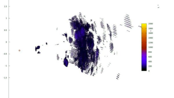
He finally arrived at a grid of 100 ultrasonic emitters controlled from an Arduino through a series of shift register boards. Using this he can steer his ultrasonic beam horizontally as well as vertically, and receive echoes from objects in three-dimensional space. The ornamental bird example he uses for his scanning tests doesn’t quite emerge in startling clarity, but it is still clear that an object of its size and rough shape is visible enough for the drone in his original idea to detect it. If you would like to experiment with the same techniques and array then all the resources can be found in a GitHub repository, meanwhile we’re still impressed with the progress from relative electronics novice to this. We hope the ideas within it will be developed further.

We’ve seen ultrasonic arrays before, but mainly used in levitation experiments.

El Cheapo Phased-Array Sonar

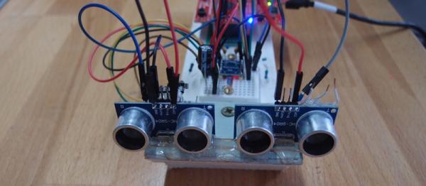
Sonar is a great sensor to add to any small-scale robot project. And for a couple bucks, the ubiquitous HC-SR04 modules make it easy to do. If you’ve ever used these simple sonar units, though, you’ve doubtless noticed that you get back one piece of information only — the range to the closest object that the speaker is pointing at. It doesn’t have to be that way. [Graham Chow] built a simple phased-array using two SR04 modules, and it looks like he’s getting decent results.

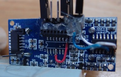
PB211200The hack starts out by pulling off the microcontroller and driving the board directly, a hack inspired by [Emil]’s work on reverse engineering the SR04s. Once [Graham] can control the sonar pings and read the results back, the fun begins.

[Graham] uses TI’s Cortex M4F LaunchPad eval kit to generate a ping and receive the reflections. With normal sonar, the time between the ping being sent and its reception is determined by the range to the target. In a phased array, in this case just the two modules, the difference in the times it takes for the ping to return to each module is used to determine the angle to the target.

phased_array_sonar_tableau

If you’re DSP-savvy, [Graham] is using a phase-shifted square wave signal so that the correlations of the sent and returned signals have better peaks. This also helps the peaks in correlation across the two SR04s in the array. We think it’s pretty awesome that [Graham] is resolving a couple of degrees in angular separation when he moved his wine bottle. With a couple more SR04 units, [Graham] could start to get height information back as well.

For not much scratch, [Graham] has himself an experimental setup that lets him play with some pretty heavy signal processing. We’re impressed, and can’t wait to see what’s next. Special thanks to [Graham] for posting up the code.

And thanks [João] for the tip!

Build A Phased-Array Radar In Your Garage That Sees Through Walls

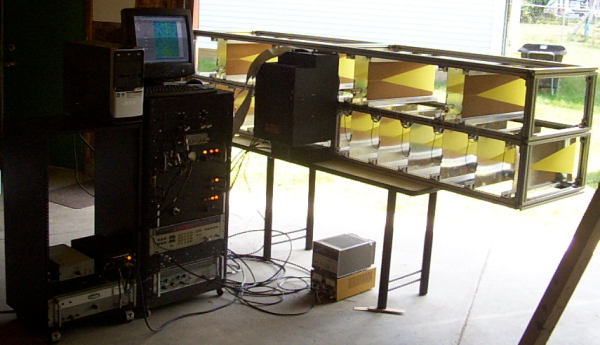
Until recently phased array radar has been very expensive, used only for military applications where the cost of survival weighs in the balance. With the advent of low-cost microwave devices and unconventional architecture phased array radar is now within the reach of the hobbyist and consumer electronics developer. In this post we will review the basics of phased-array radar and show examples of how to make low-cost short-range phased array radar systems — I built the one seen here in my garage! Sense more with more elements by making phase array your next radar project.

Phased array radar

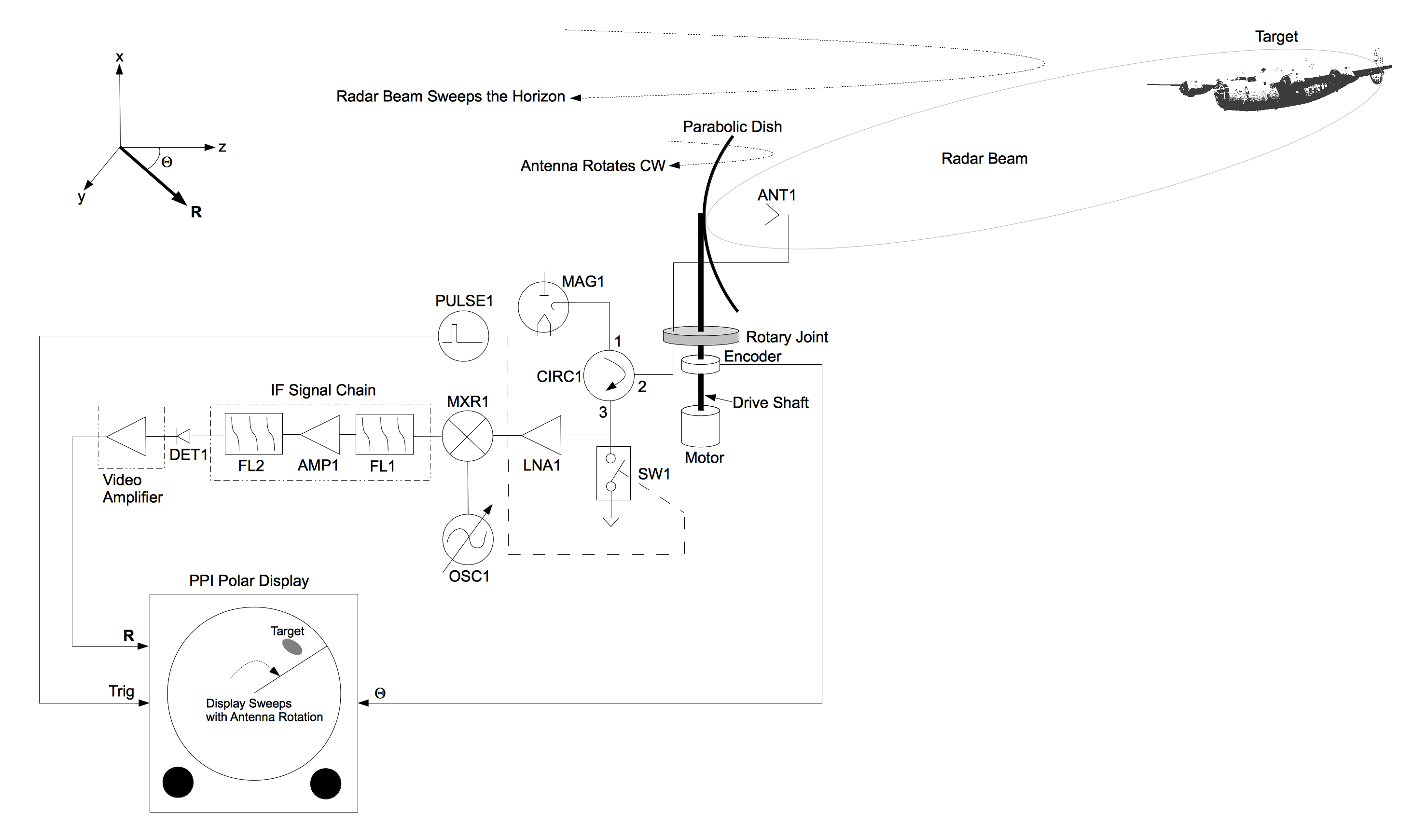
In a previous post the basics of radar were described where a typical radar system is made up of a large parabolic antenna that rotates. The microwave beam projected by this antenna is swept over the horizon as it rotates. Scattered pulses from targets are displayed on a polar display known as a Plan Position Indicator (PPI).

Block diagram of a conventional radar system using a parabolic dish.

In a phased array radar (PDF) system an array of antenna elements are used instead of the dish. These elements are phase-coherent, meaning they are all phase-referenced to the same transmitter and receiver. Each element is wired in series with a phase shifter that can be adjusted arbitrarily by the radar’s control system. A beam of microwave energy is focused by applying a phase rotation to each phase shifter. This beam can be directed anywhere within the array’s field of view. To scan the beam rotate the phases of the phase shifters accordingly. Like the rotating parabolic dish, a phased array can scan the horizon but without the use of moving parts.

Continue reading “Build A Phased-Array Radar In Your Garage That Sees Through Walls”