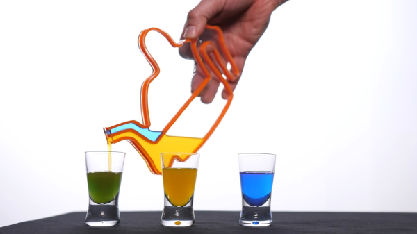
Getting Closer To Metal 3D Printing

Most of our 3D printers lay down molten plastic or use photosensitive resin. But professional printers often use metal powder, laying out a pattern and then sintering it with a laser. [Metal Matters] is trying to homebrew a similar system (video, embedded below). And while not entirely successful, the handful of detailed progress videos are interesting to watch. We particularly enjoyed the latest installment (the second video, below) which showed solutions to some of the problems.

Because of the complexity of the system, there are small tidbits of interest even if you don’t want to build a metal printer. For example, in the most recent video, a CCD camera gives up its sensor to detect the laser’s focus.

Continue reading “Getting Closer To Metal 3D Printing”

The Sony ScopeMan, Possibly The Best Product They Never Made

From the perspective of a later decade it’s sometimes quaint and amusing to look back at the technological objects of desire from times past. In the 1980s for example a handheld television was the pinnacle of achievement, in a decade during which the Walkman had edged out the transistor radio as the pocket gadget of choice it seemed that visual entertainment would surely follow. Multiple manufacturers joined the range of pocket TVs on offer, and Sony’s take on the format used a flattened CRT with an angled phosphor screen viewed from behind through its glass envelope. [Niklas Fauth] took one of these Sony Watchman devices and replaced its TV circuit board with one that turned it into a vector display. The Sony Scopeman was born!

The schematic is deceptively simple, with an ESP32 receiving audio via Bluetooth and driving the deflection coils through a pair of op-amps and a set of driver transistors. These circuits are tricky to get right though, and in this he acknowledged his inspiration. Meanwhile the software has two selectable functions: a fairly traditional X-Y vector ‘scope display and a Lorenz attractor algorithm. And of course, it can also display a vector version of our Wrencher logo.

We like the Scopeman, in fact we like it a lot. There may be some discomfort for the retro tech purist in that it relies on butchering a vintage Watchman for its operation, but we’d temper that with the observation that the demise of analogue broadcast TV has rendered a Watchman useless, and also with the prospect that a dead one could be used for a conversion project.

[Niklas] has had more than one project appear on these pages, a memorable example being his PCB Tesla coil.

Raspberry Pi Enters Microcontroller Game With $4 Pico

Raspberry Pi was synonymous with single-board Linux computers. No longer. The $4 Raspberry Pi Pico board is their attempt to break into the crowded microcontroller module market.

The microcontroller in question, the RP2040, is also Raspberry Pi’s first foray into custom silicon, and it’s got a dual-core Cortex M0+ with luxurious amounts of SRAM and some very interesting custom I/O peripheral hardware that will likely mean that you never have to bit-bang again. But a bare microcontroller is no fun without a dev board, and the Raspberry Pi Pico adds 2 MB of flash, USB connectivity, and nice power management.

As with the Raspberry Pi Linux machines, the emphasis is on getting you up and running quickly, and there is copious documentation: from “Getting Started” type guides for both the C/C++ and MicroPython SDKs with code examples, to serious datasheets for the Pico and the RP2040 itself, to hardware design notes and KiCAD breakout boards, and even the contents of the on-board Boot ROM. The Pico seems designed to make a friendly introduction to microcontrollers using MicroPython, but there’s enough guidance available for you to go as deep down the rabbit hole as you’d like.

Our quick take: the RP2040 is a very well thought-out microcontroller, with myriad nice design touches throughout, enough power to get most jobs done, and an innovative and very hacker-friendly software-defined hardware I/O peripheral. It’s backed by good documentation and many working examples, and at the end of the day it runs a pair of familiar ARM MO+ CPU cores. If this hits the shelves at the proposed $4 price, we can see it becoming the go-to board for many projects that don’t require wireless connectivity.

But you want more detail, right? Read on.

Continue reading “Raspberry Pi Enters Microcontroller Game With $4 Pico”

3D Printed Pi Arcade Is An Emulation Horn Of Plenty

Let’s be honest, building a home arcade cabinet isn’t exactly the challenge it once was. There’s plenty of kits out there that do all the hard work for you, and they even sell some pretty passable turn-key units at Walmart now. If you want to put a traditional arcade cabinet in your home, it’s not hard to get one.

Which is why this wild build by [Rafael Rubio] is so interesting. The entirely 3D printed enclosure looks like some kind of art piece from the 1970s, and is a perfect example of the kind of unconventional designs made possible by low-cost additive manufacturing. Building something like this out of wood or metal would be nightmare, especially for the novice; but with even a relatively meager desktop 3D printer you’re only a few clicks away from running off your own copy.

Removable side panels allow access to the electronics.

Inside the nautilus-like enclosure is a Raspberry Pi running Retropie, a 10″ LCD panel from Pimoroni, and a GeeekPi interface board that connects up to the 8-way joystick and arcade buttons. [Rafael] has included a Bill of Materials and an assembly overview that you can follow along with, though the cavernous internal dimensions of the enclosure certainly give you ample of room for improvisation if you’d rather blaze your own path.

Like the retro-futuristic computer terminals created by [Oriol Ferrer Mesià], this arcade machine completely reinvents a traditional design that most people take for granted. Is this layout actually better than the standard arcade cabinet? It’s not really our place to say. But it’s certainly a new and unconventional approach to “solved” problem, and that’s what we’re all about.

A One-Transistor Ham Transmitter Anyone Can Build

What attracts a lot of people to amateur radio is that it gives you the ability to make your own gear. Scratch-building hams usually start by making their own antennas, but eventually, the itch to build one’s own radio must be scratched. And building this one-transistor transmitter is just about the simplest way to dive into the world of DIY radio.

Of course, limiting yourself to eight components in total entails making some sacrifices, and [Kostas (SV3ORA)]’s transmitter is clearly a study in compromise. For starters, it’s only a transmitter, so you’ll need to make other arrangements to have a meaningful conversation. You’ll also have to learn Morse code because the minimalist build only supports continuous-wave (CW) mode, although it can be modified for amplitude modulation (AM) voice work.

The circuit is flexible enough that almost any part can be substituted and the transmitter will still work. Most of the parts are junk-bin items, although the main transformer is something you’ll have to wind by hand. As described, the transformer not only provides feedback to the transistor oscillator, but also has a winding that powers an incandescent pilot lamp, and provides taps for attaching antennas of different impedances — no external tuner needed. [SV3ORA] provides detailed transformer-winding instructions and shows the final build, which looks very professional and tidy. The video below shows the rig in action with a separate receiver providing sidetone; there’s also the option of using one of the WebSDR receivers sprinkled around the globe to verify you’re getting out.

This little transmitter looks like a ton of fun to build, and we may just try it for our $50 Ham series if we can find all the parts. Honestly, the hardest to come by might be the variable capacitor, but there are ways around that too.

Continue reading “A One-Transistor Ham Transmitter Anyone Can Build”

Oscilloscope Learns How To Speak Japanese, And VGA

Nostalgia aside, there are a few things an analog scope can still do better than a digital, with oscilloscope art being a prime example. The blue-green glow of phosphors in a real CRT just add something special to such builds, and as a practitioner of this craft, [Aaron] decided to paint a New Year’s affirmation on his oscilloscope screen, in Japanese calligraphy of all things.

When used in X-Y mode, analog oscilloscopes lend themselves nicely to vector-based graphics, which is the approach [Aaron] has taken with previous “Oscilloclock” builds, like the Metropolis Clock. The current work, however, doesn’t use vector graphics, opting instead to turn the scope into the business end of a VGA display. He had previously developed the hardware needed to convert a VGA signal into X- and Y-axis analog outputs, so the bulk of the work was rendering the calligraphy, first in ink and then scanning and processing the results into a file. In keeping with the Japanese theme, [Aaron] chose a rare scope from Nihon Tsushinki Co., Ltd., from 1963. It’s a beautiful piece of equipment and obviously lovingly restored, and with the VGA adapter temporarily connected, the four Japanese characters scroll gracefully up the screen, delivering the uplifting message: “Steady progress, day by day.

[Aaron] sure puts a lot of work into his analog scope builds, which we’ve featured a few times. Check out the clock he made from Grandpa’s old Heathkit scope, or his Tektronic vectorscope clock. And don’t forget about other forms of oscilloscope art — they can make music too, after all.

Multi-Channel Battery Monitor Aces First Sea Trial

A little over a a year ago, we covered an impressive battery monitor that [Timo Birnschein] was designing for his boat. With dedicated batteries for starting the engines, cranking over the generator, and providing power to lights and other amenities, the device had to keep tabs on several banks of cells to make sure no onboard systems were dipping into the danger zone. While it was still a work in progress, it seemed things were progressing along quickly.

But we know how it is. Sometimes a project unexpectedly goes from having your full attention to winning an all-expense-paid trip to the back burner. In this case, [Timo] only recently put the necessary finishing touches on his monitor and got it installed on the boat. Recent log entries on the project’s Hackaday.io page detail some of the changes made since the last time we checked in, and describe the successful first test of the system on the water.

Certainly the biggest issue that was preventing [Timo] from actually using the monitor previously was the lack of an enclosure and mounting system for it. He’s now addressed those points with his 3D printer, and in the write-up provides a few tips on shipboard ergonomics when it comes to mounting a display you’ll need to see from different angles.

The printed enclosure also allowed for the addition of some niceties like an integrated 7805 voltage regulator to provide a solid 5 V to the electronics, as well as a loud piezo beeper that will alert him to problems even when he can’t see the screen.

Under the hood he’s also made some notable software improvements. With the help of a newer and faster TFT display library, he’s created a more modern user interface complete with a color coded rolling graph to show voltages changes over time. There’s still a good chunk of screen real estate available, so he’s currently brainstorming other visualizations or functions to implement. The software isn’t using the onboard NRF24 radio yet, though with code space quickly running out on the Arduino Nano, there’s some concern about getting it implemented.

As we said the first time we covered this project, you don’t need to have a boat to learn a little something from the work [Timo] has put into his monitoring system. Whether you’re tracking battery voltages or temperatures reported by your BLE thermometers, a centralized dashboard that can collect and visualize that data is a handy thing to have.