Stuck at home in self-quarantine, artist and filmmaker [Kira Bursky] had fewer options than normal for her latest film project. While a normal weekend film sprint would have involved collaborating with actors, set designers, and cinematographers in a frenzied attempt to finish in less than 48 hours, she instead chose to indulge in her curiosity for projection mapping, a technique that involves projecting visuals onto three-dimensional or flat surfaces.
In order for the images to properly map onto a surface, the surface first has to be mapped so that the projection is able to properly transform the flat image in order to produce the illusion of the light wrapping around the object. The technique is done in layers, in software similar to Photoshop, making it easier for the designer to organize the different interacting components in their animation.
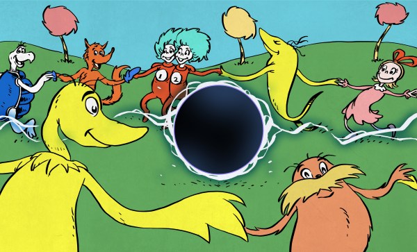
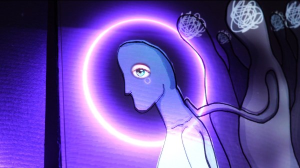
[Kira] used a tool called Lightform to design her projections, which relies on a camera to calibrate the location of the surface and a projector to display the visuals. Her animated figures are drawn with loose lines and characterized by their slow gradients and ethereal movements. In the background of her film, a rhythmic sound plays while she brings the figures closer to view. Their outlines come into greater focus until the figures transform into her physical body, which also dances with the meandering lights.
Check out the short film below.
Continue reading “Filmmaking From Home With Projection Mapping”