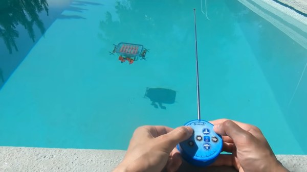
Although you’d be hard-pressed to tell in some areas, it’s summer in the northern hemisphere, which always seems to bring out the projects that require a swimming pool for adequate testing. The [Brick Experiment Channel]’s latest build, a submersible made almost entirely from Lego, is one such project and has us pining for weather that makes a dip sensible rather than suicidal.
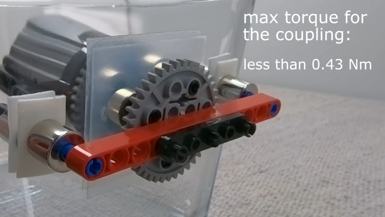
 The sub featured in the video below is a significant improvement over the “Sub in a Jug” approach the [Brick Experiment Channel] favored for version 1. Rather than starting with a vessel specifically designed not to hold water, the hull for this vessel is an IKEA food container, with a stout glass body and a flexible lid with silicone seals. And instead of penetrating the hull for driveshafts and attempting to seal them, this time around he built clever magnetic couplings.
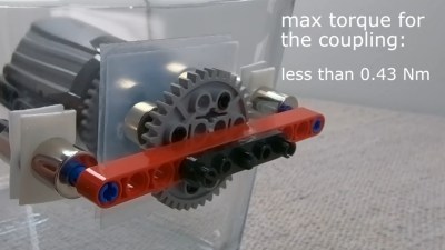
The couplings transmit torque from the motors on the inside to gears and props on the outside. And where the first version used a syringe-pump ballast tank to control the depth, this one uses vertical thrusters. The flexible lid proved to be a problem with that scheme, since it tended to collapse as the depth increased, preventing the sub from surfacing. That was solved with some Lego bracing and adjustment of the lead shot ballast used to keep the sub neutrally buoyant.
This looks like a ton of summer fun, and even if you don’t have Legos galore to work with, it could easily be adapted to other materials. There are a ton of other fun [BEC] Lego builds to check out, some of which we’ve covered, including a Lego drone and a playing card shooter.
Continue reading “Magnetic Couplings Make This Lego Submarine Watertight” →