Raspberry Pi Halloween Voice Changer

[Dave Shevett] has spent a lot of time (more than a year) expanding his Technomancer costume along with the companion (Arduino-driven) magic staff. He found, however, he needed a way to get his voice out from behind the mask. If you are going to go through that much trouble, you might as well augment your voice at the same time, right?

[Dave’s] voice changer uses a Raspberry Pi which isn’t all that complicated. The Pi uses Linux, and Unix–the predecessor to Linux–has a long history of having little tools you can string together to do big jobs. So once you have a Pi and a sound card, the rest is just some Linux command line wizardry.

There’s a battery and a small portable amplifier to get that booming voice. Since you don’t want to lug a keyboard and monitor around to handle every reboot, [Dave] set the Pi up to run his voice-changing scripts on each reboot.

This is a great example of why old Unix programmers make small tools and use the shell to join them together. [Dave’s] voice changer is pretty much just some off the shelf parts and a  script so simple it hardly qualifies as programming in any real sense. In fact, it is essentially one line of “code”:

play "|rec --buffer 2048 -d pitch -300 echos 0.8 0.88 100 0.6 150 .5 band 1.2k 1.5k"

Sure, there is some street cred in embedded development to doing everything the hard way, but with the advent of cheap embedded Linux systems, why not take advantage of the tools where you can?

If you want a more roll-your-own approach, you can pick up your Arduino or break out an audio mixer (but good luck getting it in your costume).

Steal This Ham Radio (Technology)

Although I see a lot of wireless projects, I’m always surprised at the lack of diversity in the radio portions of them. I’m a ham radio operator (WD5GNR; I was licensed in 1977) and hams use a variety of radio techniques. If you think hams just use Morse code and voice communications, you are thinking of your grandfather’s ham radio. Modern hams have gone digital and communicate via satellites, video, and many different digital techniques that could easily have applicability to different wireless projects.

Of course, Morse code may have been one of the first digital modes. But hams have used teletype, FAX, and other digital modes for years. Now with PCs and soundcards in common use, hams have been on the forefront of devising sophisticated digital radio techniques.

Continue reading “Steal This Ham Radio (Technology)”

RaspiDrums Uses Expensive Sensors

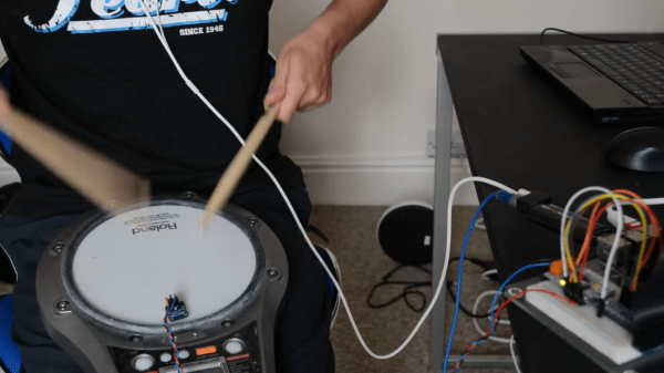
Piezoelectric sensors are great for monitoring mechanical impacts with a microcontroller. Whether you’re monitoring knocks on a door or watching a heartbeat, they are a cheap way to get the job done. They do have their downsides, though, so when [Jeremy] wanted to build an electronic drum set, he decided to use more expensive accelerometers to measure the percussive impacts instead.

Even though piezo sensors are cheap, they require a lot of work to get them working properly. The ADXL377 3-axis accelerometer that [Jeremy] found requires much less work, plus provides more reliable data due to a 1kHz low-pass filter at the output. In his setup, a Raspberry Pi handles all of the heavy lifting. An ADC on each drum sends data about each impact of the drum, and the Raspberry Pi outputs sound via the native Alsa driver and a USB sound card.

This project goes a long way to show how much simpler a project like this is once you find the right hardware for the job. [Jeremy]’s new electronic drums are very well documented as well if you are curious about using accelerometers on your newest project rather than piezo sensors. And, if you’re into drums be sure to see how you can have drums anywhere, or how you can build your own logic drums.

Continue reading “RaspiDrums Uses Expensive Sensors”

Zynq And The OPL3 Music Synthesizer

We’re big fans of the Zynq, which is an answer to the question: what do you get when you cross a big ARM processor with a big FPGA? So it isn’t surprising that [GregTaylor’s] project to emulate the OPL3 FM Synthesis chip in an FPGA using the Zynq caught our eye.

The OPL3 (also known as the Yamaha YMF262) was a very common MIDI chip on older PC sound cards. If you had a Sound Blaster Pro or 16 board, you had an OPL3 chip in your PC. The OPL3 was responsible for a lot of the music you associate with vintage video games like Doom. [Greg] not only duplicated the chip’s functions, but also ported imfplay from DOS to run on the Zynq’s ARM processors so he could reproduce those old video game sounds.

The Zybo board that [Greg] uses includes an Analog Devices SSM2603 audio codec with dual 24-bit DACs and 256X oversampling. However, the interface to the codec is isolated in the code, so it ought to be possible to port the design to other hardware without much trouble.

To better match the original device’s sampling rate with the faster CODEC, this design runs at a slightly slower frequency than the OPL3, but thanks to the efficient FPGA logic, the new device can easily keep up with the 49.7 kHz sample rate.

Using an FPGA to emulate an OPL3 might seem to be overkill, but we’ve seen worse. If you prefer to do your synthesis old school, you can probably get a bulk price on 555 chips.

Continue reading “Zynq And The OPL3 Music Synthesizer”

The Alexanderson Transmitter: Very-low Frequency Radio Rides Again!

Is your ham radio rig made of iron and steel? Is it mechanically driven? Classified as a World Heritage Site? We didn’t think so. But if you’d like to tune in one that is, or if you’re just a ham radio geek in need of a bizarre challenge, don’t miss Alexanderson Day 2015 tomorrow, Sunday, June 28th

The Alexanderson Transmitter design dates back to around 1910, before any of the newfangled tube technology had been invented. Weighing in at around 50 tons, the monster powering the Varberg Radio Station is essentially a high-speed alternator — a generator that puts out 17.2 kHz instead of the 50-60 Hz  that the electric companies give us today.

Most of the challenge in receiving the Alexanderson transmitter broadcasts are due to this very low broadcast frequency; your antenna is not long enough. If you’re in Europe, it’s a lot easier because the station, SAQ, is located in Sweden. But given that the original purpose of these behemoths was transcontinental Morse code transmission, it only seems sporting to try to pick it up in the USA. East Coasters are well situated to give it a shot.

And of course, there’s an app for that. The original SAQrx VLF Receiver and the extended version both use your computer’s sound card and FFTs to extract the probably weak signal from the noise.

We scouted around the net for an antenna design and didn’t come up with anything more concrete than “few hundred turns of wire in a coil” plugged into the mic input.  If anyone has an optimized antenna design for this frequency, post up in the comments?

Thanks [Martin] for the tip!

Hackaday Prize Entry: Dr. DAC

The theme of this year’s Hackaday Prize is. ‘build something that matters.’ A noble goal, but there’s also a second prize – the Best Product prize – that is giving $100k to one lucky team who can appeal to people with open jaws and wallets. It’s a fabulous prize that also includes a six month residency at the Hackaday Design Lab, but right now there aren’t many contenders for this part of The Hackaday Prize.

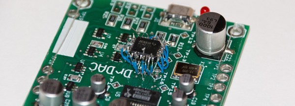
[drewrisinger]’s DrDAC USB Audio DAC is one of those project that’s in the running for the Best Product prize. He’s solving the problem of terrible low-quality built-in soundcards that seem to be everywhere. Yes, it’s a simple idea, but the execution is great.

The electronics for DrDAC are pretty much what you would expect for a DIY audio sound card; A PCM2706 takes USB audio and sends it out over I2S. A PCM1794 converts the I2S to analog audio, and an OPA2836  amplifies it and sends everything out through a 1/8″ jack or a pair of RCA plugs.

[drewrisinger] started DrDAC as a school project, and after receiving the PCBs, he noticed a problem. MultiSim’s footprint for a TQFP-32 package was too small, meaning the IC simply wouldn’t fit on the board. It was too late in the semester to order a new board, meaning some sort of rework needed to happen. [drew] fixed this problem by soldering jumper wires between the pads to the leads of the chip. Yes, it looks crazy, but apparently it works. You can check out a video of that whole process below.


The 2015 Hackaday Prize is sponsored by:

Continue reading “Hackaday Prize Entry: Dr. DAC”

A DIY Fourier Transform Spectrometer

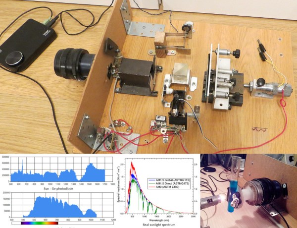
Typical spectrometers use prisms or diffraction gratings to spread light over a viewing window or digital sensor as a function of frequency. While both prisms and gratings work very well, there are a couple of downsides to each. Diffraction gratings produce good results for a wide range of wavelengths, but a very small diffraction grating is needed to get high-resolution data. Smaller gratings let much less light through, which limits the size of the grating. Prisms have their own set of issues, such as a limited wavelength range. To get around these issues, [iliasam] built a Fourier transform spectrometer (translated), which operates on the principle of interference to capture high-resolution spectral data.

[iliasam]’s design is built with an assortment of parts including a camera lens, several mirrors, a micrometer, laser diode, and a bunch of mechanical odds and ends. The core of the design is a Michelson interferometer which splits and recombines the beam, forming an interference pattern. One mirror of the interferometer is movable, while the other is fixed. [iliasam]’s design uses a reference laser and photodiode as a baseline for his measurement, which also allows him to measure the position of the moving mirror. He has a second photodiode which measures the interference pattern of the actual sample that’s being tested.

Despite its name, the Fourier transform spectrometer doesn’t directly put out a FFT. Instead, the signal from both the reference and measurement photodiodes is passed into the sound card of a computer. [iliasam] wrote some software that processes the sampled data and, after quite a bit of math, spits out the spectrum. The software isn’t as simple as you might think – it has to measure the reference signal and calculate the velocity of the mirror’s oscillations, count the number of oscillations, frequency-correct the signal, and much more. After doing all this, his software calculates an interferogram, performs an inverse Fourier transform, and the spectrum is finally revealed. Check out [iliasam]’s writeup for all the theory and details behind his design.