Rotating Lithophane Box Turns With Time

If you wanted to make a rotating display box, what would you use to make it spin? A servo? A stepper motor? [ChrisN219] didn’t need his to move quickly by any means, and this opened up his options to something we probably wouldn’t have thought to use: a clock movement. Specifically, the hour minute part of the shaft.

Rotating lithophanes of your loved ones makes for a pretty cool project, and there isn’t a whole lot to this build to make it difficult. Much of it is 3D printed, including the tube in the center that the LED strip is wrapped around. The base is just big enough to hold the clock movement and the LED strip controller, so it would fit nicely on a desk or a mantel.

This is version two of [Chris]’ lithophane box, which gave him a chance to perfect the frame and design a thicker center post to withstand the heat from the LED strip. All the files are available if you want to print your own panels and take them for a spin. Since it’s so easy to change them out, you may end up with a big pile to choose from.

Remote controlled Billy from the Saw movies

Pi-Controlled Billy From The Saw Horror Flicks

[David0429] has made a very scary Raspberry Pi controlled puppet. Scary that is if you’ve seen the Saw movies where a serial killer uses one like it, called Billy, to communicate with his victims. If you haven’t, then it’s a pretty neat remote-controlled puppet-on-a-tricycle hack.

A stepper motor hidden under the front fender moves the trike by rotating the front wheel. It does this using a small 3D printed wheel that’s attached to the motor’s shaft and that presses against the trike’s wheel. Steering is done using a 3D printed gear mounted above the fender and attached to the steering column. That gear is turned by a servo motor through another gear. And another servo motor in the puppet’s head moves its mouth up and down.

All these servos and motors are wired to an Adafruit stepper motor HAT stacked on a Raspberry Pi hidden under the seat. Remote control is done from a webpage in any browser. The Flask python web framework runs on the Pi to both serve up the webpage and communicate with it in order to receive commands.

[David0429] took great care to make the puppet and tricycle look like the one in the movie. Besides cutting away excess parts of the trike and painting it, he also ran all the wires inside the tubular frame, drilling and grinding out holes where needed.  The puppet’s skeleton is made of wood, zip ties and hinges but with the clothes on, it’s pretty convincing. Interestingly, the puppet in the first movie was constructed with less sophistication, having been made out of paper towel rolls and papier-mâché. The only things [david0429] would like to do for next time are to quieten the motors for maximum creepiness, and to make it drive faster. However, the need for a drive system that could be hidden under the fender resulted one that could only work going slowly. We’re thinking maybe driving it using the rear wheels may make it possible provide both speed and stealth. Ideas anyone?

In any case, as you can see in the video below, the result is suitably creepy.

Continue reading “Pi-Controlled Billy From The Saw Horror Flicks”

Rotating Frame Will Change Your View Of Vertical Images

[Tim] was tired of compromising his portrait-oriented digital photos by shoehorning them into landscape-only frames. Unable to find a commercial solution, he built his own rotating digital photo frame from a 27″ LCD TV.

It uses a Raspi 3 to find [Tim]’s pictures on a giant SD card. He originally wanted to have the Pi pull pictures from Google Photos and display them randomly, but the API doesn’t work in that direction. Instead, a Python script looks at the pictures on the SD card and determines whether each is landscape or portrait-oriented. If a picture was taken in portrait-mode, the display will rotate 90 degrees. Rotation is handled with an Arduino, a stepper motor, and some 3D-printed herringbone gears. The first version was a bit noisy, so [Tim] re-printed the motor mount and the pinion gear out of flexible filament.

[Tim] designed the mount and frame himself and laser-cut the pieces out of birch plywood. We like that he accounted for the front-heaviness and that he covered the high voltage circuitry with acrylic to mitigate the risk of shock. All the code and design files are available on his project page. Make the jump to see a brief demonstration followed by a walk-through and stay for the six-minute slide show.

Continue reading “Rotating Frame Will Change Your View Of Vertical Images”

Red Carpet BB-8 internals

How BB-8 Works Revealed At Star Wars Celebration Europe

Finally the workings of the official BB-8 that you’ve seen rolling around at various events have been revealed. Its makers [Matt Denton] and [Josh Lee] participated in an hour-long presentation at Star Wars Celebration Europe 2016 just this past week where the various views of its internals were shown in action. It’s since had BB-8 builders (yours truly included) analyzing the workings for new ideas. We also now have the official name for it, red carpet BB-8.

For the first half of their talk they went over how BB-8 was implemented for Star Wars: The Force Awakens. As we’ve long known this was done using 7 puppeted BB-8’s, though it was revealed that only 4 were actually used, including a stationary one called the wiggler whose purpose you can guess. Another thing we didn’t know is that they did consider building a working BB-8 for filming but decided they needed something bullet proof, that would work right every time without making a film crew wait for repairs, and so went with the puppets instead.

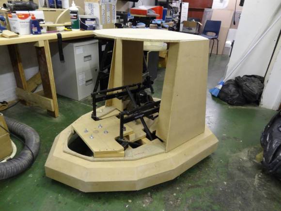
The second half of their talk contained the big reveal, the mechanism inside red carpet BB-8’s ball. It turns out to be pretty close to what many builders have been doing. If you’ve seen the DIYer’s guide to the different BB-8 drive systems then you’ll understand when we say it’s a pendulum drive (aka axle drive). That is, there’s a motorized axle that crosses the middle of the ball and the ball rotates on that axle. Meanwhile a large mass suspended below the axle acts as the pendulum mass.

BB-8 builders have known the importance of keeping as much mass as possible as low down as possible for stability, but it was revealed the great extent to which that has been done in the red carpet version. Motors for the head’s pitch and yaw are located at the bottom and their motion is transferred up to the center using what are maybe best known as bicycle brake cables. Another big reveal was a linear actuator for the body roll, tilting the center stuff with respect to the mass lower down. The actuator itself is located in the lower section. Also, BB-8 builders have been mounting the drive motors for rotating the ball with respect to the axle, in line with the axle. However, in red carpet BB-8 the motor is also at the bottom and its motion appears to be transferred up to the axle via belt and worm gears. You may mistake the gold cylinders on either side of the central gimbal system to be motors but they’re actually Moflon slip rings.

Those are just a few of the insights gained so far from analyzing the video below. Doubtless people will be noticing a lot more in the weeks to come.

Continue reading “How BB-8 Works Revealed At Star Wars Celebration Europe”

Pump Up The Volume With Lead Shot And LEDs

One of the redeeming qualities of many modern cheap keyboards is the built-in volume control buttons. But this is Hackaday, and many of us (and you) have Model Ms or newfangled mechanical keyboards that only have the essential keys. Those multimedia buttons only adjust the system volume anyway. We would bet that a lot of our readers have sweet sound systems as part of their rig but have to get up to change the volume. So, what’s the solution? Build a color-changing remote USB volume knob like [Markus] did.

Much like the Instructable that inspired him, [Markus] used a Digispark board and a rotary encoder. The color comes from a WS2812 LED ring that fits perfectly inside a milky plastic tub that once held some kind of cream. When the volume is adjusted, the ring flashes white at each increment and then slowly returns to whatever color it’s set to. Pushing the button mutes the volume.

The components are pretty lightweight, and [Markus] didn’t want the thing sliding all over the desk. He took an interesting approach here and filled the base with the lead from a shotgun round and some superglue. The rotating part of the button needed some weight too, so he added a couple of washers for a satisfying feel. Be sure to check out the demonstration after the break.

Digispark board not metal enough for you? Here’s a volume knob built around a bare ATtiny85 (which is the same thing anyway).

Continue reading “Pump Up The Volume With Lead Shot And LEDs”

tachtastic diy tachometer

Fantastic Tach Is Strangely Called Tachtastic

We all have projects from yesteryear that we wish had been documented better. [EjaadTech] is fighting back by creating a project page about a tachometer he built 3 years ago while in college. He’s done a great write-up documenting all the steps from bread-boarding to testing to finished project. All of the code necessary for this tachometer is available too, just in case you’d like to make one yourself.

At the heart of the project is an AVR ATMega8 chip that performs the calculations and controls the LCD output screen that displays both the immediate RPM as well as the average. To hold everything together, [EjaadTech] etched his own custom PCB board that we must say looks pretty good. In addition to holding all the necessary components, there is also an ISP connector for programming and re-programming.

There are two attachment options for sensing the RPM. One is a beam-break style where the IR emitter is on one side of the object and the receiver is on the other. This type of sensor would work well with something like a fan, where the blades would break the IR beam as they passed by. Then other attachment has the IR emitter and receiver on one board mounted next to each other. The emitter continually sends out a signal and the receiver counts how often it sees a reflection. This works for rotating objects such as shafts where there would not be a regular break in the IR beam. For this reflective-based setup to work there would have to be a small piece of reflective tape on the shaft providing a once-per-revolution reflection point. Notice the use of female headers to block any stray IR beams from causing an inaccurate reading… simple and effective.

Wiimote Controlled Extermination: Dalek-Style

Dalek Build

Convention-goers have likely strolled past a number of Daleks: the aliens drive around the event space, spouting threats of extermination and occasionally slapping folks with a rotating eyestalk. [James Bruton] has been hard at work building this Wii-remote-controlled Dalek with his fellow hackers at the SoMakeIt Hackerspace (you may remember our write-up from earlier this year).

Most Dalek builds seat a driver inside the body at the helm of a salvaged electric wheelchair, where they plunk around using a joystick control and simmer in an increasingly potent aroma. This version started like most, with a wooden structure from plans sourced at Project Dalek. Inside, however, [James] and his crew have tapped into the wheelchair’s motor controller to feed it a PWM signal from an Arduino Shrimp, which is linked to a Raspi. The Pi receives a Bluetooth signal from a Wiimote, and, through their custom Python script, directs the Dalek with ease.

They’re still working on finishing the Dalek’s body, but they’re using some clever tactics to push onward: using a 3D-printer to solve some of the nuanced styling choices. They’ve uploaded a gallery with additional photos on Facebook, and you can watch them goofing around with their creation (losing their balance and nearly exterminating themselves) in a video after the break.

Continue reading “Wiimote Controlled Extermination: Dalek-Style”