It was Elliot and Dan on the podcast today, taking a look at the best the week had to offer in terms of your hacks. We started with surprising news about the rapidly approaching Supercon keynote; no spoilers, but Star Trek fans such as we who don’t have tickets will be greatly disappointed.
Elliot waxed on about taking the poop out of your prints (not pants), Dan got into a camera that adds a dimension to its images, and we both delighted in the inner workings of an air-powered squishy robot.
Questions? We’ve got plenty. Is it possible to take an X-ray without an X-ray tube? Or X-rays, for that matter? Did Lucille Ball crack a spy ring with her fillings? Is Algol set to take over the world? What’s inside a germanium transistor? How does a flipping fish say Happy Birthday? And how far down the Meshtastic rabbit hole did our own Tom Nardi fall? Tune in to find out the answers.
I modified a printer a few years ago to handle multiple filaments, but I will admit it was more or less a stunt. It worked, but it felt like you had to draw mystic symbols on the floor of the lab and dance around the printer, chanting incantations for it to go right. But I recently broke down and bought a color printer. No, probably not the one you think, but one that is pretty similar to the other color machines out there.
Of course, it is easy to grab ready-made models in various colors. It is also easy enough to go into a slicer and “paint” colors, but that’s not always desirable. In particular, I like to design in OpenSCAD, and adding a manual intervention step into an otherwise automatic compile process is inconvenient.
The other approach is to create a separate STL file for each filament color you will print with. Obviously, if your printer can only print four colors, then you will have four or fewer STLs. You import them, assign each one a color, and then, if you like, you can save the whole project as a 3MF or other file that knows how to handle the colors. That process is quick and painless, so the question now becomes how to get OpenSCAD to put out multiple STLs, one for each color.
But… color()
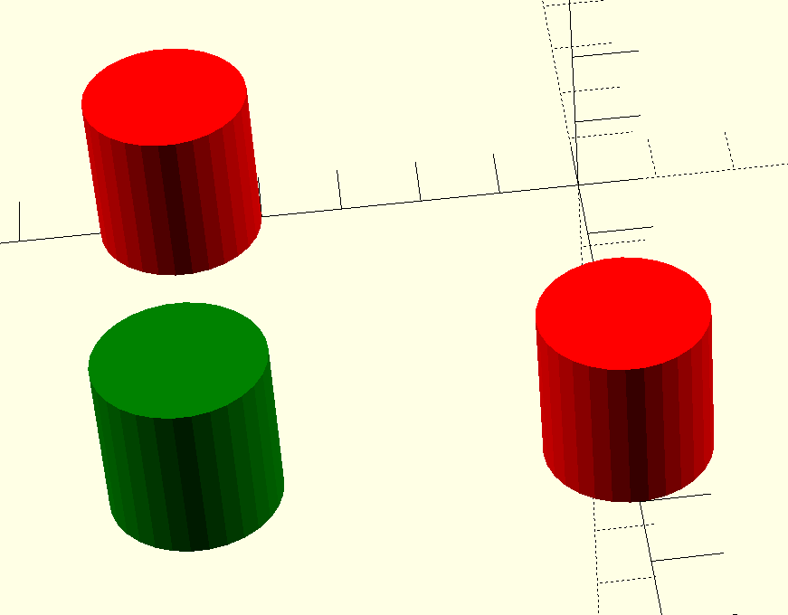
OpenSCAD has a color function, but that just shows you colors on the screen, and doesn’t actually do anything to your printed models. You can fill your screen with color, but the STL file you export will be the same. OpenSCAD is also parametric, so it isn’t that hard to just generate several OpenSCAD files for each part of the assembly. But you do have to make sure everything is referenced to the same origin, which can be tricky.
OpenSCAD Development Version Test
It turns out, the development version of OpenSCAD has experimental support for exporting 3MF files, which would allow me to sidestep the four STLs entirely. However, to make it work, you not only have to run the development version, but you also have to enable lazy unions in the preferences. You might try it, but you might also want to wait until the feature is more stable.
Besides, even with the development version, at least as I tried it, every object in the design will still need its color set in the slicer. The OpenSCAD export makes them separate objects, but doesn’t seem to communicate their color in a way that the slicer expects it. If you have a large number of multi-color parts, that will be a problem. It appears that if you do go this way, you might consider only setting the color on the very top-most objects unless things change as the feature gets more robust.
A Better Way
What I really wanted to do is create one OpenSCAD file that shows the colors I am using on the screen. Then, when I’m ready to generate STL files, I should be able to just pick one color for each color I am using.
Everyone loves colourful 3D prints, but nobody loves prime towers, “printer poop” and all the plastic waste associated with most multi-material setups. Over the years, there’s been no shortage of people trying to come up with a better way, and now it’s time for [Roetz] to toss his hat into the ring, with his patent-proof, open-source Roetz-End. You can see it work in the video below.
The Roetz-End is, as you might guess, a hot-end that [Roetz] designed to facilitate directional material printing. He utilizes SLM 3D printing of aluminum to create a four-in-one hotend, where four filaments are input and one filament is output. It’s co-extrusion, but in the hot-end and not the nozzle, as is more often seen. The stream coming out of the hot end is unmixed and has four distinct coloured sections. It’s like making bi-colour filament, but with two more colours, each aligned with one possible direction of travel of the nozzle.
What you get is ‘directional material deposition’: which colour ends up on the outer perimeter depends on how the nozzle is moving, just like with bi-color filaments– though far more reliably. That’s great for making cubes with distinctly-coloured sides, but there’s more to it than that. Printing at an angle can get neighboring filaments to mix; he demonstrates how well this mixing works by producing a gradient at (4:30). The colour gradients and combinations on more complicated prints are delightful.
Is it an MMU replacement? Not as-built. Perhaps with another axis– either turning the hot-end or the bed to control the direction of flow completely, so the colours could mix however you’d like, we could call it such. That’s discussed in the “patent” section of the video, but has not yet been implemented. This technique also isn’t going to replace MMU or multitool setups for people who want to print dissimilar materials for easily-removable supports, but co-extruding materials like PLA and TPU in this device creates the possibility for some interesting composites, as we’ve discussed before.
As for being “patent-proof” — [Roetz] believes that through publishing his work on YouTube and GitHub into the public domain, he has put this out as “prior art” which should block any entity from successfully filing a patent. It worked for Robert A. Heinlein with the waterbed, but that was a long time ago. Time will tell if this is a way to revive open hardware in 3D printing.
It’s certainly a neat idea, and we thank [CityZen] for the tip.
In the original Animal Crossing from 2001, players are able to interact with a huge cast of quirky characters, all with different interests and personalities. But after you’ve played the game for awhile, the scripted interactions can become a bit monotonous. Seeing an opportunity to improve the experience, [josh] decided to put a Large Language Model (LLM) in charge of these interactions. Now when the player chats with other characters in the game, the dialogue is a lot more engaging, relevant, and sometimes just plain funny.
How does one go about hooking a modern LLM into a 24-year-old game built for an entirely offline console? [josh]’s clever approach required a lot of poking about, and did a good job of leveraging some of the game’s built-in features for a seamless result.
Last time, we built a case for a PCB that handles 100 W of USB-C power, an old project that I’ve long been aiming to revive. It went well, and I’d like to believe you that the article will give you a much-needed easy-to-grasp FreeCAD introduction, Matrix knowledge upload style, having you designing stuff in no time.
Apart from my firm belief in the power of open-source software, I also do believe in social responsibilities, and I think I have a responsibility to teach you some decent FreeCAD design practices I’ve learned along the way. Some of them are going to protect your behind from mistakes, and some of them will do that while also making your project way easier to work with, for you and others.
You might not think the last part about “others” matters, but for a start, it matters in the ideal world that we’re collectively striving towards, and also, let’s be real, things like documentation are half intended for external contributors, half for you a year later. So, here’s the first FreeCAD tip that will unquestionably protect you while helping whoever else might work with the model later.
Okay, we’re all hackers, so I’ll start with zero-th FreeCAD tip – press Ctrl+S often. That’ll help a ton. Thankfully, FreeCAD’s autorecovery system has made big leaps, and it’s pretty great in case FreeCAD does crash, but the less you have to recover, the better. Now, onto the first tip.
As the art of 3D printing has refined itself over the years, a few accessories have emerged to take prints to the next level. One of them is the threaded insert, a a piece of machined brass designed to be heat-set into a printed hole in the part. They can be placed by hand with a soldering iron, or for the really cool kids, with a purpose-built press. They look great and they can certainly make assembly of a 3D printed structure very easy, but I’m here to tell you they are not as necessary as they might seem. There’s an alternative I have been using for years which does essentially the same job without the drama. Continue reading “No Need For Inserts If You’re Prepared To Use Self-Tappers”→
Ask a Hackaday scribe who’s helped run the lightning talks at one of our events, and they’ll tell you that keeping the speakers on time is a challenge. Conversely if the staffer is trying to indicate to the speaker how much time they have left, it must be difficult from the podium to keep track while delivering your talk. Fortunately there’s [makeTVee] waiting in the wings with a solution, a cube whose faces each have a custom 5×7 LED matrix on them. The countdown is clear and unambiguous, and should provide no distractions.
The brains behind it all is a XIAO nRF52840 Sense board using the Zephyr RTOS, the LEDs are WS2812s on their own PCBs, and the party piece is only revealed at the end of the countdown. A tilt mechanism triggered by a servo releases a ball bearing down a track, where it hits a telephone bell and provides a very audible reminder to the speaker. The result saw action during the lightning talks at the Hackaday Europe event earlier in the year, but it’s taken a while for the write-up to make it online.