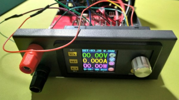
In 2019, it’s possible to kit out a lab with all the essentials at an even cheaper price than it has ever been. The DPS3005 is one such example of low-cost equipment – a variable power supply available for less than $50 with a good set of features. [Markel Robregado] wanted a little more functionality, however, and got down to work.
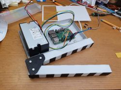
The crux of [Markel]’s project is improved connectivity. A Texas Instruments CC2640R2F Launchpad is employed to run the show, with its Bluetooth Low Energy capability coming in handy. A custom smartphone app communicates with the Launchpad, which then communicates with the power supply over its Serial Modbus interface. Through the app, [Markel] can set the voltage and current limit on the power supply, as well as switch it on and off. This could prove useful, particularly for remote triggering in the case of working with dangerous projects. Sometimes it pays to take cover, after all.
We’ve seen power supplies modified before; this pot mod for higher precision is a particular treat. If you’ve hacked your bench hardware for better performance, let us know. Video after the break.
Continue reading “Adding Bluetooth Control To A Benchtop Power Supply”