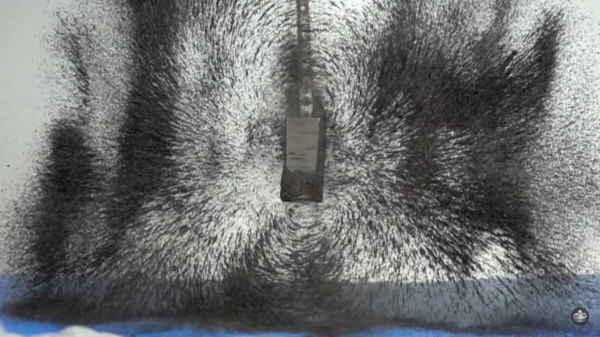
If you need help visualizing magnetic fields, these slow-motion video captures should educate or captivate you. Flux lines are difficult to describe in words, because magnet shape and strength play a part. It might thus be difficult to visualize what is happening with a conical magnet, for a person used to a bar magnet. We should advise you before you watch the video below the break, if you are repelled by the sight of magnetite sand clogging a bare magnet then flying on the floor, this is your only warning.
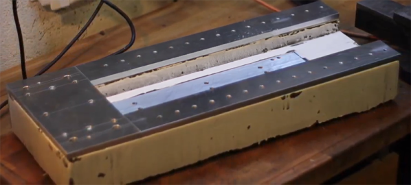
The technique and equipment are simple and shown in the video. A layer of black sand is spread on a piece of tense plastic to make something like a dirty trampoline, and a neodymium magnet is dropped in the middle. The bouncing action launches the sand and magnet simultaneously so they are hanging in the air and the particles can move with little more than air resistance.
These videos were all taken with a single camera and a single magnet. Multiple cameras would yield 3D visuals, and the intertwining fields of multiple magnets can be beautiful. Perhaps a helix of spherical magnets? What do you have lying around the hosue? In a twist, we can use magnets to simulate gas atoms and trick them into performing unusual feats.