When it comes to rotary encoders, there are plenty of options. Most of them involve putting a credit card number into an online vendor’s website, though, and that’s sometimes just not in the cards. In that case building your own, like this encoder using magnetic spheres, is a pretty cool way to go too.
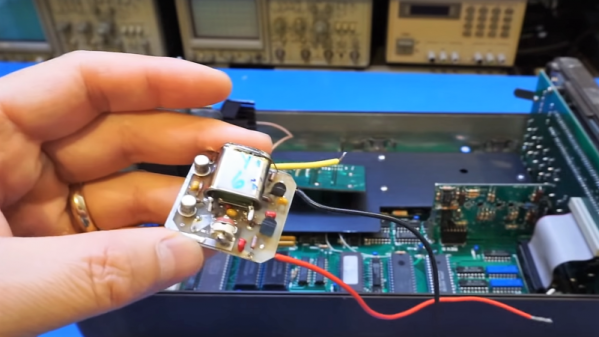
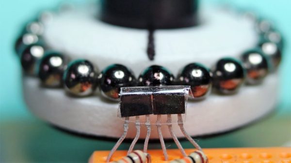
If he’d had less time to spare, we imagine [Antonio Ospite] would have gone for a commercial solution rather than building an encoder from scratch. Then again, he says his application had noise considerations, so maybe this was the best solution overall. He had some latching Hall effect sensors lying around, but lacked the ring magnet that is usually used with such sensors in magnetic encoders. But luckily, he had a mess of magnetic spheres, each 5 mm in diameter. Lined up in a circle around a knob made from a CD spindle, the spheres oriented themselves with alternating poles, which is just what the Hall sensors want to see. The sensors were arranged so the pulses are 90° apart, and can resolve 4.29° steps. Check out the video below to watch it work.
Small, cheap and effective are always good things. But magnets aren’t the only thing behind homebrew rotary encoders. A couple of microswitches might do in a pinch, or maybe even scrapped hard drives would suffice.
Continue reading “Magnetic Spheres Line Up For Rotary Encoder Duty”