Outdoor navigation is a problem that can be considered solved for decades or maybe even centuries, depending on the levels of accuracy, speed and accessibility required. Indoor navigation and location, on the other hand, is a relatively new field and we are still figuring it out. Currently there are at least four competing technologies pushed by different manufacturers. One is ultra wide band radio and [Marco van Nieuwenhoven] shows us what a beacon using this technology is made of.
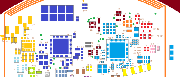
In his thorough tear down of an Estimote location beacon, he comes up with a complete parts list and schematics for each of the four PCB layers. The beacons are controlled by a Cortex M4 and feature Bluetooth radio in addition to the UWB part. They also come with a three-axis accelerometer, temperature, ambient light and pressure sensors and NFC capability. These boards combine a lot of functionality in a compact package and [Marco]’s stated intent is to create an open source firmware for them.
Hacking proprietary hardware, especially when doing so in public may get you in legal trouble, but in this case [Marco] has contacted the manufacturer, and the relationship seems to be friendly so far. Let’s hope it stays that way; these things look like a promising platform and may become a lower cost alternative to the evaluation kit running the same UWB radio we featured earlier. Alternatively you could ditch the UWB and use WiFi for indoor location.