We love our 3D printers. But sometimes we really wish we could print in metal. While metal printing is still out of reach for most of us, HRL Labs announced a powdered aluminum printing process that they claim is a breakthrough because it allows printing (and welding) of high-strength aluminum alloys that previously were unprintable and unweldable.
The key is treating the metal with special zirconium-based nanoparticles. The nanoparticles act as nucleation sites that allow the aluminum to form the correct microstructure. The full paper on the process appears in Nature.
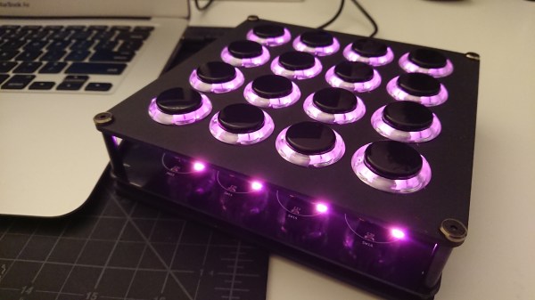
Musicians have an array of electronic tools at their disposal to help make music these days. Some of these are instruments in and of themselves, and [Wai Lun] — inspired by the likes of Choke and Shawn Wasabi — built himself a midi fighter
Midi fighters are programmable instruments where each button can be either a note, sound byte, effect, or anything else which can be triggered by a button. [Lun]’s is controlled by an ATmega32u4 running Arduino libraries — flashed to be recognized as a Leonardo — and is compatible with a number of music production programs. He opted for anodized aluminum PCBs to eliminate flex when plugging away and give the device a more refined look. Check it out in action after the break!
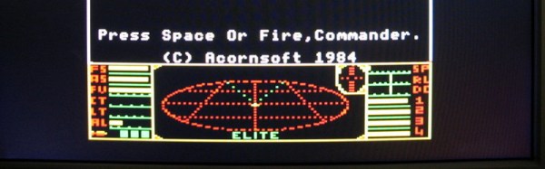
In the early 1980s, there were a plethora of 8-bit microcomputers on the market, and the chances are that if you were interested in such things you belonged to one of the different tribes of enthusiasts for a particular manufacturer’s product. If you are British though there is likely to be one machine that will provide a common frame of reference for owners of all machines of that era: The Acorn BBC Microcomputer which was ubiquitous in the nation’s schools. This 6502-driven machine is remembered today as the progenitor and host of the first ARM processors, but at the time was notable for the huge array of built-in interfaces it contained. Its relatively high price though meant that convincing your parents to buy you one instead of a ZX Spectrum was always going to be an uphill struggle.
So, you never owned a BBC Micro, and this has scarred you for life. Never mind, all is not lost, for now you can have that Acorn experience without scouring eBay for a classic micro, by running one entirely in silicon on a myStorm FPGA board.
To be fair, running classic hardware on an FPGA is nothing new and there have been a few BBC Micros implemented in this way, not to mention an Acorn Atom. But this project builds on the previous FPGA BBC Micros by porting it entirely to Verilog and incorporating some of the bug fixes from their various forks. There are screenshots of the result running several classic games, as well as test screens and a benchmark revealing it to be a faithful reproduction of a 2MHz BBC Micro.
This year at Maker Faire, laser cutters were all the rage. Dremel announced a 40W laser cutter, but it won’t be available for purchase until this time next year, there is no price yet, and therefore doesn’t deserve further mention. Glowforge was out in full force, but the most interesting aspect of the Glowforge — a compact filter system that sits right underneath the laser — was not to be found. It looks like lasers are the next 3D printer.
Of course, those in the know have already been using laser cutters for years, and there are options for desktop CO2 laser cutters that cost less than a kilobuck. I speak, of course, of the ubiquitous K40 laser, a machine you can get off of eBay or AliExpress for the price of a generic, off-brand 3D printer. There is a downside to the K40, though: the control electronics and software are notoriously terrible. Fix that, though, and you have something really spectacular.
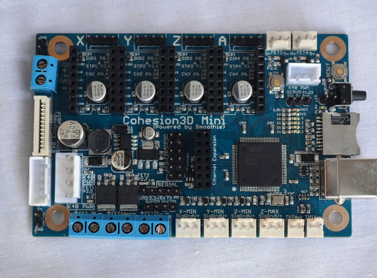
The Cohesion3D Mini
This year at Maker Faire, [Ray Kholodovsky] of Cohesion3D brought out his Smoothie-derived control boards for CNC machines and laser cutters. Of note is his K40 upgrade that turns the eBay special laser cutter into a 32-bit professional machine. This is the cheapest way to start lasing in your workshop.
We saw [Ray] at the Faire last year when he was demoing his Smoothie-derived boards for 3D printers and CNC machines. These are tiny, relatively low-cost boards that use Smoothieware, an Open Source, 32-bit CNC control system that is extremely extensible and very powerful. Basically, if you’re building a normal, ordinary DIY 3D printer, a RAMPS or RAMBO will do. If you’re doing something weird, like a 3D printer with strange kinematics, a 5-axis milling machine, or you’d like awesome engraving on a laser cutter, Smoothie is the way to go.
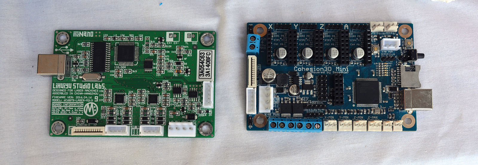
The stock board found in a K40 (left) and the Cohesion3D Mini (right). The Cohesion3D Mini is a drop-in replacement for the stock K40 board.
The Cohesion3D board is a direct, drop-in replacement for the control board found in the K40 laser. Since all of the K40 laser cutters are the same, and they’re really only a power supply and a CNC gantry, this is the one-stop-shop of K40 upgrades. The terrible electronics are gone, you don’t have to use Corel, and for a hundred bucks, you have something resembling a professional laser cutter.
The K40 laser has been around for several years now, but only recently have a few very interesting hacks and mods come out that push this blue light special laser cutter into semi-professional territory for people willing to get their hands dirty. A few months ago [Scorch] published K40 Whisperer, a piece of software that makes the stock electronics tolerable and able to accept normal SVGs and DXFs. The K40 has also been modified for a larger bed, and LaserWeb has been handling the software side of things for about two years now. Things are looking great for the K40 hacking scene, and Hackaday already has a, ‘I just bought a K40, now what?’ series in the works. Things are looking up for cheap laser cutters, and a Smoothie upgrade is just the cherry on top.
This is it. After twelve years we finally have a new Star Trek. Star Trek: Discovery (we’re using ST:DSC as the abbreviation) is airing right about when this post goes up. Next week, you’ll have to pay CBS $6USD a month to get your Star Trek fix, and today might be the last time a new episode of Star Trek is aired on broadcast TV ever. Enjoy it now, and hope the theme song doesn’t have lyrics. Also, hope The Orville is a tenth as good as a Galaxy Quest series could be.
What’s the best way to describe Delta Sigma PLLs? The Cat In The Hat (PDF, page 31). [Dr. Tune] found a Seuss reference in a TI app note. Personally, I’m a fan of hand-drawn cartoons, but we’ll take what we can get.
The Raspberry Pi is a great media storage device, but it’s absolutely insufficient for audiophile tomfoolery. Here’s a neat Pi DAC/amp/DSP thingy. The VoltaStream turns the Raspberry Pi into a WiFi-connected pair of speakers with low-latency audio in and a TOSLINK connector.
How was the World Maker Faire in New York this weekend? In one word, empty. Abnormally so. Maker Faire was not as crowded as last year, and you could actually move around. My agoraphobia didn’t kick in until the afterparties, and lines for the $5 bottles of water were short. Bay Area Faire attendance was down 16% from 2016-2017, and I would bet attendance for the NY Faire would be down a similar amount. Even a 10% decline in attendance would be noteworthy; the weather last year was cold and rainy and this year was beautiful. There are rumors, speculation, and people wondering how long Maker Faire will continue, but except for Intel pulling out of the maker market, no actual information. Millennials are killing the Maker Faire industry?
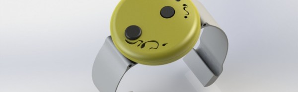
I’ve fallen and I can’t get up. We all remember it, and we all know what product we’re talking about. Now, with cheap microcontrollers, ubiquitous WiFi, and wearable electronics, there must be a simpler solution. [Jean Paradedel]’s emergency button project is designed to replace those wearable emergency buttons, which usually include an expensive call center plan.
[Jean]’s button is based off an ESP8266 module, which sends an email to a care provider if a button is pressed. The whole thing is powered by a CR2032 watch battery and the device’s case was 3D printed. The interface is simple — it’s just a wearable button, after all — and the form factor is small enough to be completely unobtrusive.
[Jean] reflashed the ESP8266 board with a simple sketch that runs the project. First, a button-press connects the device to WiFi and then blinks an LED so you know it’s connected. When the emergency button is pressed, an email is sent out letting a caregiver know that there’s a problem.
Check out the video below for a demo of this cheap emergency button in action.
Our friends at [The Thought Emporium] have been bringing us delightful projects but not all of them warrant a full-fledged video. What does anyone with a bevy of small but worthy projects do? They put them all together like so many mismatched LEGO blocks. Grab Bag #1 is the start of a semi-monthly video series which presents the smaller projects happening behind the scenes of [The Thought Emporium]’s usual video presentations.
Solar eclipse? There are two because the first was only enough to whet [The Thought Emporium]’s appetite. Ionic lifters? Learn about the favorite transformer around the shop and see what happens when high voltage wires get too close. TEA lasers? Use that transformer to make a legitimate laser with stuff around your house. Bismuth casting? Pet supply stores may have what you need to step up your casting game and it’s a total hack. Failures? We got them too.