If you have a well-equipped shop, it isn’t unusual to have a welder. Stick welders have become a commodity and even some that use shield gas are cheap if you don’t count buying the bottle of gas. But plasma cutters are still a bit pricey. Can you get one from China for under $300? Yes. Do you want one that cheap? [Metal Massacre Fab Shop] answers that question in the video below.
First impressions count, and having plasma misspelled on the unit (plasme) isn’t promising. The instructions were unclear, and some of the fittings didn’t make him happy, so he replaced them with some he had on hand. He also added some pipe tape to stop any leaking.
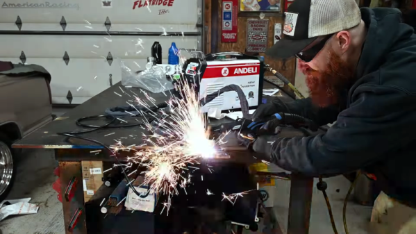
The first test was a piece of quarter-inch steel at 35 amps. The machine itself is rated to 50 amps. Sparks ensued, and with a little boost in amperage, it made a fair-looking cut. At 50 amps, it was time to try a thicker workpiece. It made the cut, although it wasn’t beautiful. The leaking regulator and the fact that he can’t run the compressor simultaneously as the cutter didn’t help.
From the look of it, for light duty, this would be workable with a little practice and maybe some new fittings. Unsurprisingly, it probably isn’t as capable as a professional unit. Still could be very handy to have.
It is possible to convert a welder into a plasma cutter. A handheld unit like this probably won’t benefit from a Sharpie.