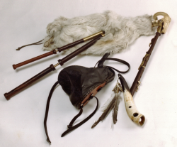
Bagpipes are an instrument at least a millennia old, the most popular of which, in modern times, is the Great Highland bagpipe. There are other types of bagpipes, some of which have a bellows rather than requiring the player to manually inflate the bag by breathing into it. The advantage of the bellows is that it delivers dry air to the bag and reed (instead of the moist air from the player’s breath) and this dryness means that the instrument stays in tune better and the reed lasts longer.
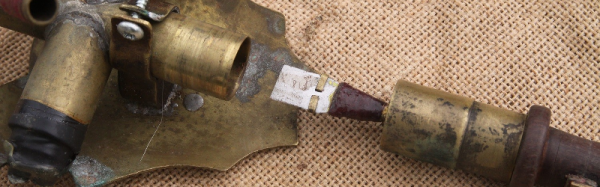
 [TegwynTwmffat] has built his own Irish uilleann pipes, (one of the types that use a bellows) using a carbon steel chanter (the part with the finger holes) and a steel reed. The reed vibrates and a pickup is used to convert this vibration into an electric signal, similar to the way a guitar pickup converts a vibrating string into an electric signal. This means that the signal from [Tegwyn]’s pipes can be sent to an amplifier. It also means that the signal can be processed the same way as the signal from an electric guitar – through distortion, flanger, wah, or delay pedals, for example.
[Tegwyn] has put up a drawing of the chanter showing dimensions and locations of the holes and has posted a couple of songs so you can hear the pipe in action. The first has the pipes without any effects on them, the second with effects. The comments for the second say that there are no electric guitars in the song – it’s all the pipes! Bagpipes seem to be a (relatively) popular instrument to hack and we’ve seen a couple of them over the years, such as this one made from duct tape, and this one – an electronic version.
Continue reading “Hackaday Prize Entry: Electro-Magnetic Enabled Bagpipes”


 To remedy the abrupt movements, [Daniel Holden et. al] recently