The oft-quoted saying “all models are wrong, but some are useful” is a tounge-in-cheek way of saying that at some level, tools we use to predict how the world behaves will differ from reality in some measurable way. This goes well beyond the statistics classroom it is most often quoted in, too, and is especially apparent to anyone who has used a GPS mapping device of any sort. While we might think that our technological age can save us from the approximations of maps and models, there are a number of limitations with this technology that appear in sometimes surprising ways. [Kyle] has an interesting writeup about how maps can be wrong yet still be incredibly useful especially in the modern GPS-enabled world. Continue reading “Misleading GPS, Philosophy Of Maps, And You”→
IO user [monte] was pointed towards an 1898 display patent issued to a [George Mason] and liked the look of the ‘creepy’ font it defined. The layout used no less than 21 discrete segments to display the complete roman alphabet and numerals, which is definitely not possible with the mere seven segments we are all familiar with. [monte] then did the decent thing and created a demonstration digit using modern parts.
For the implementation, [monte] created a simple PCB by hand (with an obvious mistake) and 3D-printed an enclosure and diffuser to match. After a little debugging, a better PCB was ordered from one of the usual overseas factories. There isn’t a schematic yet, but they mention using a CH32V003 Risc-V micro, which can be seen sitting on the rear of the PCB.
Maximum flexibility is ensured by storing every glyph as a 32-bit integer, with each LED corresponding to a single bit. It’s interesting to note the display incorporates serifs, which are definitely optional, although you could display sans-serif style glyphs if you wanted to. There is now a bit of a job to work out how to map character codes to glyph codes, but you can have a go at that yourself here. It’s still early doors on this project, but it has some real potential for a unique-looking display.
There’s something magical about volumetric displays. They really need to be perceived in person, and no amount of static or video photography will ever do them justice. [AncientJames] has built a few, and we’re reporting on his progress, mostly because he got it to run a playable port of DOOM.
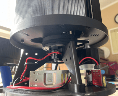
Base view of an earlier version showing the motor drive and PSU
As we’ve seen before, DOOM is very much a 3D game viewed on a 2D display using all manner of clever tricks and optimizations. The background visual gives a 3D effect, but the game’s sprites are definitely very solidly in 2D land. As we’ll see, that wasn’t good enough for [James].
The basic concept relies on a pair of 128 x 64 LED display matrix modules sitting atop a rotating platform. The 3D printed platform holds the displays vertically, with the LEDs lined up with the diameter, meaning the electronics hang off the back, creating some imbalance.
Lead, in the form of the type used for traditional window leading, was used as a counterbalance. A Raspberry Pi 4 with a modified version of this LED driver HAT is rotating with the displays. The Pi and both displays are fed power from individual Mini560 buck modules, taking their input from a 12 V 100 W Mean-Well power supply via a car alternator slip ring setup. (Part numbers ABH6004S and ASL9009 for those interested.) Finally, to synchronise the setup, a simple IR photo interrupter signals the Pi via an interrupt.
Additive manufacturing (AM) has been getting a lot of attention over the years, with its use in construction a recurring theme. Generally this brings to mind massive 3D printers that are carted to construction sites and assemble entire homes on the spot. That’s the perspective with which a recent ZDNet article by [Rajiv Rao] opens, before asking whether AM in construction is actually solving any problems. As [Rajiv] notes, the main use of such on-site AM construction is for exclusive, expensive designs, such as ICON’s House Zero which leans into the extruded concrete printing method.
Their more reasonable Wolf Ranch residential homes in Texas also use ICON’s Vulcan II printer to print walls out of concrete, with a roof, electrical wiring, plumbing, etc. installed afterwards. Prices for these Wolf Ranch 3 to 4 bedroom houses range from about $450,000 to $600,000, and ICON has been contracted by NASA to work a way to 3D print structures on the Moon out of regolith.
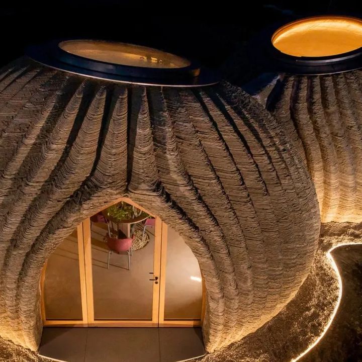
3D printed home by WASP out of clay. (Credit: WASP)
Naturally, none of these prices are even remotely in the range of the first-home buyers, or the many economically disadvantaged who make up a sizable part of the population in the US and many other nations in the Americas, Africa, etc. To make AM in construction economically viable, it would seem that going more flatpack and on-site assembly is the way to go, using the age-old pre-fabrication (prefab) method of constructions.
This is the concept behind the University of Maine’s BioHome3D, which mainly uses PLA, wood fiber and similar materials to create modules that contain insulation in the form of wood fiber and cellulose. These modules are 3D printed in a factory, after which they’re carted off to the construction site for assembly, pretty much like any traditional prefab home, just with the AM step and use of PLA rather than traditional methods.
Prefab is a great way to speed up construction and already commonly used in the industry, as modules can have windows, doors, insulation, electrical wiring, plumbing, etc. all installed in the factory, with on-site work limited to just final assembly and connecting the loose bits. The main question thus seems to be whether AM in prefab provides a significant benefit, such as in less material wasted by working from (discarded) wood pulp and kin.
While in the article [Rajiv] keeps gravitating towards the need to use less concrete (because of the climate) and make homes more affordable through 3D printing, AM is not necessarily the panacea some make it out to be, due to the fact that houses are complex structures that have to do much more than provide a floor, walls and a roof. If adding a floor (or two) on top of the ground floor, additional requirements come into play, before even considering aspects like repairability which is rarely considered in the context of AM construction.
It may be the last gasp of summer here in the Northern Hemisphere, but it’s always cold somewhere, whether it’s outdoors or inside. If you suffer from cold, stiff hands, you know how difficult it can be to work comfortably on a computer all day. Somehow, all that typing and mousing does little to warm things up. What you need are hand warmers, obviously, and they might as well be smart and made to fit your hands.
Fifteen-year-old [Printerforge] created these bad boys in an effort to learn how to code LCDs and control heat like Magneto controls ferrous metals. Thanks to digital control, they can heat up to specific temperatures, and they happen to run for a long time.
Power-wise, these warmers use a 18650 cell and a TP4056 charging module. Everything is controlled by an Arduino Nano, which reads from both a thermistor and a potentiometer to control the output.
[Printerforge] really thought this project through, as you’ll see in the Instructable. There’s everything from a table of design requirements to quick but thorough explanations of nichrome wire and basic electronic theory.
And then there’s the material consideration. [Printerforge] decided that polymer clay offers the best balance of heat conductivity and durability. They ended up with two styles — flat, and joystick grip. The best part is, everything can fit in a generous pocket.
You know, it feels as though it’s getting more and more difficult to compete for Father of the Year around here. And [Jon Petter Skagmo] just laid down a new gauntlet — the incredibly overly-engineered kids car.
While the original plan was to build the entire car from scratch, [Jon] eventually opted to use an off-the-shelf car that had a dead battery.
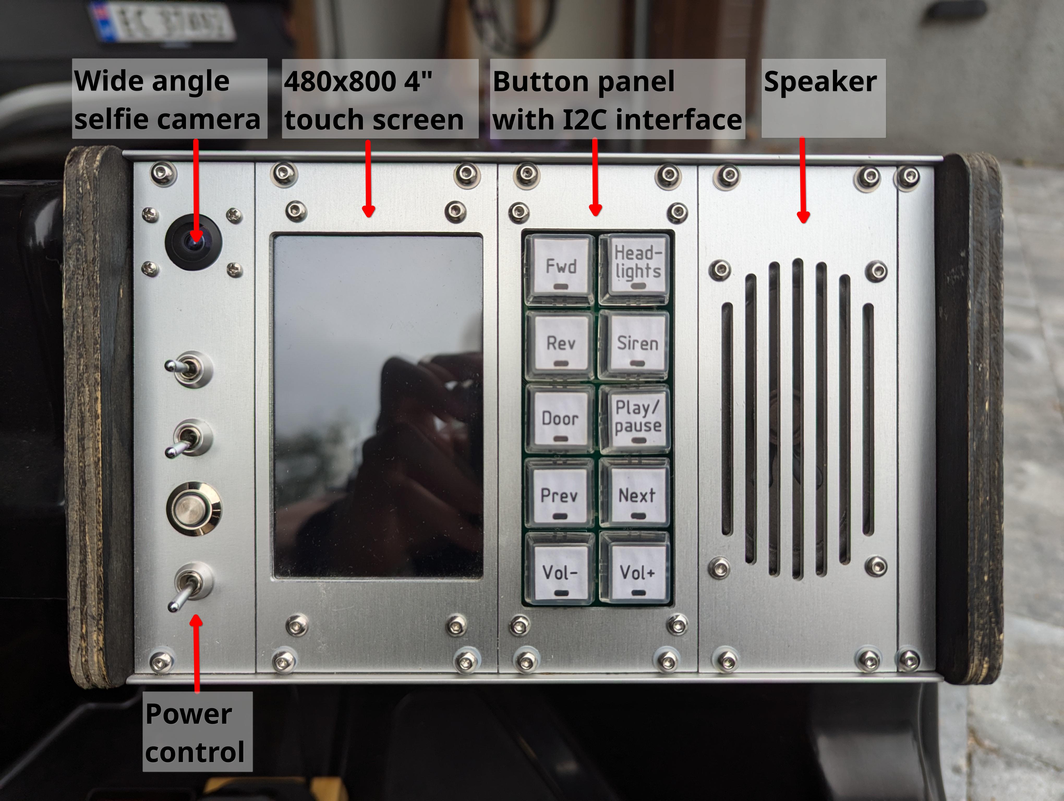
While the original architecture was quite simple, the new hardware has just about everything a kid could want in a tricked-out ride, most of which is accessible through the really cool dashboard.
We’re talking headlights, a music player, a siren, a selfie video cam that doubles as two-way communication with the driver, and even a garage door opener that uses an MQTT connection.
Under the cute little hood is where you’ll find most of the electronics. The car’s brain is a Raspberry Pi 3B, and there’s a custom daughter board that includes GPS/GNSS. This was originally meant to geofence [Baby Girl Skagmo] in, but Dad quickly realized that kids are gonna kid and disabled it pretty soon after.
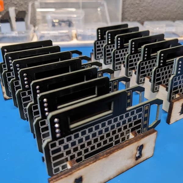
Printed circuit boards are typically only something you’d find in a digital watch. However, as [IndoorGeek] demonstrates, you can put them to wonderful use in a classical analog watch, too. They can make the perfect watch dial!
Here’s the thing. A printed circuit board is fundamentally some fiberglass coated in soldermask, some copper, maybe a layer of gold plating, and with some silk screen on top of that. As we’ve seen a million times, it’s possible to do all kinds of artistic things with PCBs; a watch dial seems almost obvious in retrospect!
[IndoorGeek] steps through using Altium Designer and AutoCAD to layout the watch face. The guide also covers the assembly of the watch face into an actual wrist watch, including the delicate placement of the movement and hands. They note that there are also opportunities to go further—such as introducing LEDs into the watch face given that it is a PCB, after all!
It’s a creative way to make a hardy and accurate watch face, and we’re surprised we haven’t seen more of this sort of thing before. That’s not to say we haven’t seen other kinds of watch hacks, though; for those, there have been many. Video after the break.