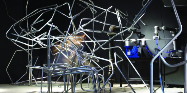
In an ambitious and ingenious blend of mechanical construction and the art of dance, [Syuko Kato] and [Vincent Huyghe] from The Bartlett School of Architecture’s Interactive Architecture Lab have designed a robotic system that creates structures from a dancer’s movements that they have christened Fabricating Performance.
A camera records the dancer’s movements, which are then analyzed and used to direct an industrial robot arm and an industrial CNC pipe bending machine to construct spatial artifacts. This creates a feedback loop — dance movements create architecture that becomes part of the performance which in turn interacts with the dancer. [Huyghe] suggests an ideal wherein an array of metal manipulating robots would be able to keep up with the movements of the performer and create a unique, fluid, and dynamic experience. This opens up some seriously cool concepts for performance art.
It’s no surprise that things change as we age, and that tasks that were once trivial become difficult. Case in point: my son asked for help with the cord on his gaming headset the other night. The cable had broken and we could see frayed conductors exposed. When I got it apart, I found that I could barely see the ultra-fine wires to resolder them after cutting out the bad section. I managed to do it, but just barely.
This experience got me thinking about how to deal with the inevitable. How do you stay active as a hacker once your body starts to fight you more than it helps you? I’m interested mostly in dealing with changes in vision, but also in loss of dexterity and fine motor skills, and dealing with cognitive changes. This isn’t a comprehensive list of the ravages of time, but they’re probably the big ones that impact any hacker-related hobby. I enlisted a couple of my more seasoned Hackaday colleagues, [Bil] and [Rud], for their tips and tricks to deal with these issues.
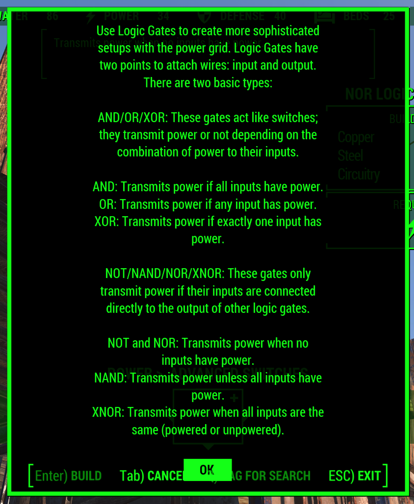
Fallout logic. This is literally called Fallout logic. This is far more confusing than it should be.
Fallout 4, the latest tale of post-apocalyptic tale of wasteland wanderers, got its latest DLC yesterday. This add-on, Contraptions Workshop, adds new objects and parts to Fallout 4‘s settlement-building workshop mechanic. This add-on brings more building pieces, elevators, and most importantly logic gates to Commonwealth settlements.
The Fallout logic gates are used in conjunction with electric generators, lights, and automated sentries used to build settlements. Although a simple NAND would do, there are several types of logic gates including AND, OR, XOR, NOT, NAND, NOR, and XNOR.
The in-game explanation for these gates is very, very weird. AND, OR, and XOR “transmit power or not depending on the combination of power to their inputs”. NOT, NAND, NOR, and XNOR are apparently different, “only transmitting power if their inputs are connected directly to the output of other logic gates”. The reason for this arbitrary distinction between different sets of gates is currently unknown except to a few programmers and project leaders at Bethesda. It should be noted {AND, OR, XOR} is not functionally complete.
With implementations of logic gates in video games comes some very interesting if useless applications. Already Fallout 4 has light boxes, allowing for huge animated billboards. Fallout speakers, the wasteland’s equivalent of Minecraft’s note block, can be used to play simple melodies. You can do anything with a NAND, so we would expect automated, sequenced versions of animated billboards and monophonic synthesizers to appear in short order.
Functional completeness can add a lot to a game. Since Minecraft added redstone logic to the game, we’ve seen some very, very impressive block-based builds. The Minecraft CPU generally regarded as being the first, most complete CPU took about three months to design and build. This build didn’t use later additions to the redstone toolbox like repeaters, pistons, and the now-cheaty command blocks.
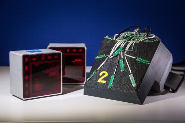
Just in case anyone secretly had the idea that Valve Software’s VR and other hardware somehow sprang fully-formed from a lab, here are some great photos and video of early prototypes, and interviews with the people who made them. Some of the hardware is quite raw-looking, some of it is recognizable, and some are from directions that were explored but went nowhere, but it’s all fascinating.
An early AR prototype that worked like looking through a tube into another world.
The accompanying video (embedded below) has some great background and stories about the research process, which began with a mandate to explore the concepts of AR and VR and determine what could be done and what was holding things back.
One good peek into this process is the piece of hardware shown to the left. You look into the lens end like a little telescope. It has a projector that beams an image directly into your eye, and it has camera-based tracking that updates that image extremely quickly.
The result is a device that lets you look through a little window into a completely different world. In the video (2:16) one of the developers says “It really taught us just how important tracking was. No matter [how you moved] it was essentially perfect. It was really the first glimpse we had into what could be achieved if you had very low persistence displays, and very good tracking.” That set the direction for the research that followed.
While faking BLE advertising beacons using an nRF24L01+ module is nothing new, it’s become a heck of a lot easier now that [Pranav Gulati] has written some library code and a few examples for it.
[Pranav]’s work is based on [Dmitry Grinberg]’s epic bit-banging BLE research that we featured way back in 2013. And while the advertisement channel in BLE is limited in the amount of data it can send, a $1 nRF24 module and a power-thrifty microcontroller would be great for a battery-powered device that needs to send small amount of data infrequently for a really long time.
We’re not 100% sure where [Pranav] is going to take this project. Honestly, the library looks like it’s ready to use right now. If you’ve been holding off on making your own BLE-enabled flock of birds, or even if you just want to mess around with the protocol, your life has gotten a lot easier.
After a certain age, computers start to show signs that they might need to be replaced or upgraded. After even more time, it starts getting hard to find parts to replace the failing components. And, as the sands slip through the hourglass, the standards used to design and build the computer start going obsolete. That’s the situation that [Drygol] found himself in when he was asked to build a SD-card hard drive for an Atari.
The 8-bit Atari in question was a fixture of home computing in the 80s. In fact, if you weren’t on the Commodore train, it’s likely that your computer of choice was an Atari. For the nostalgic among us, a new hard drive for these pieces of history is a great way to relive some of the past. Working off of information from the SIO2SD Wiki page, [Drygol] used the toner transfer method to build a PCB, 3D printed a case, and got to work on his decades-old computer.
Resurrecting old hardware is a great way to get into retrocomputing. Old protocols and standards are worth investigating because they’re from a time where programmers had to make every bit count, and there are some gems of genius hidden everywhere. Whether you’re reworking SIO from an old Atari, or building a disk emulator for an Apple ][, there are lots of options.
When a neighbor decided to cut down a walnut tree, [voluhar] decided to make something of the wood. The result was this custom keyboard that combines wood and metal in a lovely and functional package.
Walnut is a wood with a rich heritage in consumer electronics. Back in the early days of TV, huge console sets were built into solid walnut cabinets and proudly displayed along with the other fine furnishings in a home. [voluhar]’s keyboard captures a little of that spirit while retaining all the functionality you’d expect. From the custom PCB to the engraved aluminum key caps, it looks like every part was machined with a CNC router. The keyboard sports satisfyingly clicky Cherry MX switches, and a few cleverly positioned LEDs provide subtle feedback on the state of the locking keys. As for the imperfections in the walnut case, we think it just adds to the charm and warmth of the finished product, which would look great on any desktop.