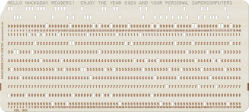
Car Driving Simulators For Students, Or: When Simulators Make Sense

There are many benefits to learning to fly an airplane, drive a racing car, or operate some complex piece of machinery. Ideally, you’d do so in a perfectly safe environment, even when the instructor decides to flip on a number of disaster options and you find your method of transportation careening towards the ground, or the refinery column you’re monitoring indicating that it’s mere seconds away from going critical and wiping out itself and half the refinery with it.

Still, we send inexperienced drivers in cars onto the roads each day as they either work towards getting their driving license, or have passed their driving exam and are working towards gaining experience. It is this inexperience with dangerous situations and tendency to underestimate them which is among the primary factors why new teenage drivers are much more likely to end up in crashes, with the 16-19 age group having a fatal crash nearly three times as high as drivers aged 20 and up.

After an initial surge in car driving simulators being used for students during the 1950s and 1960s, it now appears that we might see them return in a modern format.

Continue reading “Car Driving Simulators For Students, Or: When Simulators Make Sense”

The Neo6502 Is A Credit-Card Sized Retro Computer

The venerable MOS Technology 6502 turned up in all kinds of computers and other digital equipment over the years. Typically, it was clocked fairly slow and had limited resources, but that was just how things used to be. Today, the 6502 can run at an altogether quicker pace, and the Neo6502 was the board built to take it there.

The Neo6502 from [Olimex] is a credit-card sized retro computer built around the W65C02. If you’re unfamiliar with that chip, it’s essentially a 6502 that can go fast. How fast? It can be readily overclocked to a blazing 16 MHz, if you’re so inclined!

Unlike some 6502 retro builds, the Neo6502 doesn’t live so firmly in the past. It’s outfitted with an HDMI video interface to make it easy to hook up to modern monitors, so you needn’t fuss around with old displays. Similarly, it has a USB host port to accept input from a keyboard, and audio out via a 3.5 mm jack. There’s also a tiny PCB-mount speaker, as well as I2C, SPI, and UART interfaces. Finally, there’s 2 MB of flash onboard, and a 40-pin connector hosting all the 6502 signals that you know and love. Which is all of them. Much of this lavish equipment comes courtesy of an RP2040 microcontroller onboard that handles all the bits and bobs that aren’t fit for the CPU itself.

It’s still a new project, with things like a BASIC interpreter currently in development and boards not yet openly available.  But, if you’ve always wanted to play with a hotshot 6502, this could be the board for you. Try out the emulator and see how you go.

Continue reading “The Neo6502 Is A Credit-Card Sized Retro Computer”

A credit card-sized PCB with two sensing pads and a small OLED display

Card/IO Is A Credit Card-Sized, Open Source ECG Monitor

Of all the electrical signals generated by the human body, those coming from the heart are probably the most familiar to the average person. And because it’s also quite simple to implement the required sensors, it makes sense that electrocardiogram (ECG) machines are a popular choice among introductory medical electronics projects. [Dániel Buga], for instance, designed a compact ECG system the size of a credit card, cleverly dubbed Card/IO, that clearly demonstrates how to implement a single-lead ECG.

Although obviously not a medical-grade instrument, it still contains all the basic components that make up a proper biosignal sensing system. First, there are the sensing pads, which sense the voltage difference between the user’s two thumbs and simultaneously cancel their common-mode voltage with a technique called Right Leg Driving (RLD). The differential signal then goes through a low-pass filter to remove high-frequency noise, after which it enters an ADS1291 ECG analog front-end chip.

The ADS1291 contains a delta-sigma analog-to-digital converter as well as an SPI bus to communicate with the main processor. [Dániel] chose an ESP32-S3, programmed in Rust, to interface with the SPI bus and drive a 1″ OLED display that shows the digitized ECG signal. It also runs the user interface, which is operated using the ECG sensing pads: if you touch them for less than five seconds, the device goes into menu mode and the two pads become buttons to scroll through the different options.

All source code, as well as KiCad files for the board, can be found on the project’s GitHub page. If you’re just getting started in the biosensing field, you might also want check out this slightly more advanced project that includes lots of relevant safety information.

Continue reading “Card/IO Is A Credit Card-Sized, Open Source ECG Monitor”

LaForge Demystifies ESIM

This talk at Chaos Communications Camp 2023 is probably everything you want to know about eSIM technology, in just under an hour. And it’s surprisingly complicated. If you’ve never dug into SIMs before, you should check out our intro to eSIMs first to get your feet wet, but once you’re done, come back and watch [LaForge]’s talk.

In short, the “e” stands for “embedded”, and the eSIM is a self-contained computer that virtualises everything that goes on inside your plain-old SIM card and more. All of the secrets that used to be in a SIM card are stored as data on an eSIM. This flexibility means that there are three different types of eSIM, for machine-to-machine, consumer, and IoT purposes. Because the secret data inside the eSIM is in the end just data, it needs to be cryptographically signed, and the relevant difference between the three flavors boils down to three different chains of trust.

Whichever eSIM you use, it has to be signed by the GSM Alliance at the end of the day, and that takes up the bulk of the talk time in the end, and in the excellent Q&A period at the end where the hackers who’ve obviously been listening hard start trying to poke holes in the authentication chain. If you’re into device security, or telephony, or both, this talk will open your eyes to a whole new, tremendously complex, playground.

Running A Modern Graphics Card In A 33 MHz PCI Slot

If you ever looked at a PCI to PCIe x16 adapter and wondered what’d happen if you were to stick a modern PCIe GPU in it, the answer apparently is ‘it works’ according to an attempt by [Circuit Rewind]. As long as you accept needing to supply external power with even a low-end GT 1030 card – as the PCI slot cannot provide enough power – and being limited to a single PCIe lane. This latter point isn’t so much of an issue as a single PCIe lane offers more bandwidth than the (shared) PCI bus anyway.

Despite the somewhat improvised setup, the GT 1030 card provided a decent 1080p experience in a range of games, after removing half of the 8 GB of system RAM before the configuration would work, probably due to VRAM mapping issues. Since the mainboard used also offered PCIe, the same card was run in a PCIe x4 slot, as well as in an x1 configuration, both with noticeably higher performance and putting the ‘why’ in ‘try’.

Perhaps unsurprisingly, a RTX 3080 also booted fine with external power and only 4 GB system RAM installed. Despite the PCIe x1 link, the system was able to finish a 3D benchmark and play Doom 2016, but with only 4 GB of system RAM and an old Athlon quad-core CPU, it was a terrible experience. Perhaps the most fascinating lesson to learn from this is that PCI and PCIe are amazingly compatible with only a simple translation bridge, even if high-performance graphics aren’t quite what PCI was meant for. After all, that’s why we got cursed with AGP for many years.

Continue reading “Running A Modern Graphics Card In A 33 MHz PCI Slot”

PCIe For Hackers: Our M.2 Card Is Done

We’ve started designing a PCIe card last week, an adapter from M.2 E-key to E-key, that adds an extra link to the E-key slot it carries – useful for fully utilizing a few rare but fancy E-key cards. By now, the schematic is done, the component placement has been figured out, and we only need to route the differential pairs – should be simple, right? Buckle up.

Getting Diffpairs Done

PCIe needs TX pairs connected to RX on another end, like UART – and this is non-negotiable. Connectors will use host-side naming, and vice-versa. As the diagram demonstrates, we connect the socket’s TX to chip’s RX and vice-versa; if we ever get confused, the laptop schematic is there to help us make things clear. To sum up, we only need to flip the names on the link coming to the PCIe switch, since the PCIe switch acts as a device on the card; the two links from the switch go to the E-key socket, and for that socket’s purposes, the PCIe switch acts as a host.

While initially routing this board, I absolutely forgot about one more important thing for PCIe – series capacitors on every data pair, on the host TX side of the link. We need three capacitor pairs here – on TX of the PCIe switch uplink, and two pairs on TX side of the switch – again, naming is host-side. I only remembered this after having finished routing all the diffpairs, and, after a bit of deliberation, I decided that this is my chance to try 0201 capacitors. For that, I took the footprints from [Christoph]‘s wonderful project, called “Effect of moon phase on tombstoning” – with such a name, these footprints have got to be good.

We’ve talked about differential pair calculations before in one of the PCIe articles, and there was a demo video too! That said, let’s repeat the calculations on this one – I’ll show how to get from “PCB fab website information” to “proper width and clearance diffpairs”, with a few fun shortcuts. Our setup is, once again, having signals on outer layers, referenced to the ground layer right below them. I, sadly, don’t yet understand how to calculate differential impedance for signal layers sandwiched between two ground planes, which is to say – if there’s any commenters willing to share this knowledge, I’d appreciate your input tremendously! For now, I don’t see that there’d be a tangible benefit to such an arrangement, anyway.

Continue reading “PCIe For Hackers: Our M.2 Card Is Done”

PCIe For Hackers: An M.2 Card Journey

I’ve designed a few M.2 adapters for my own and my friends’ use, and having found those designs online, people have asked me for custom-made adapters. One of these requests is quite specific – an adapter that adds one more PCIe link to an E-key M.2 slot, the kind of slot you will see used in laptops for WiFi cards.

See, the M.2 specification allows two separate PCIe links connected to the E-key slot; however, no WiFi cards use this apart from some really old WiGig-capable ones, and manufacturers have long given up on connecting a second link. Nevertheless, there are some cards like the Google Coral M.2 E-key dual AI accelerator and the recently announced uSDR, that do indeed require the second link – otherwise, only half of their capacity is available.

It’s not clear why both Google and WaveletSDR designed for a dual-link E-key socket, since those are a rare occurrence; for the Google card, there are plenty of people complaining that the board they bought just doesn’t fully work. In theory, all you need to do to help such a situation, is getting a second PCIe link from somewhere, then wiring it up to the socket – and a perfect way to do it is to get a PCIe switch chip. You will lose out on some bandwidth because the uplink PCIe connection of the switch can only go so fast; for things like this AI accelerator, it’s not much of a problem since the main point is to get the second device accessible. For the aforementioned SDR, it might turn out useless, or you might win some but lose some – can’t know until you try! Continue reading “PCIe For Hackers: An M.2 Card Journey”