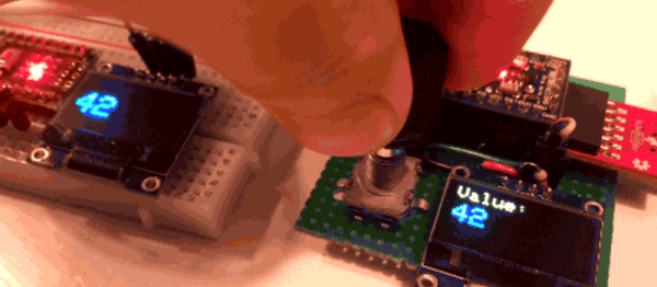
PJON, pronounced like the iridescent sky rats found in every city, is a cool one wire protocol designed by [gioblu].
[gioblu] wasn’t impressed with the complications of I2C. He thought one-wire was too proprietary, too complicated, and its Arduino implementations did not impress. What he really wanted was a protocol that could deal with a ton of noise and a weak signal in his home automation project with the smallest amount of wiring possible.
That’s where is his, “Padded Jittering Operative Network,” comes in. It can support up to 255 Arduinos on one bus and its error handling is apparently good enough that you can hold an Arudino in one hand and see the signals transmitted through your body on the other. The fact that a ground and a signal wire is all you need to run a bus supporting 255 devices and they’ll play nice is pretty cool, even if the bandwidth isn’t the most extreme.
Aside from the cool of DIY protocols. We really enjoyed reading the wiki describing it. Some of the proposed uses was running your home automation through your ducting or water pipes (which should be possible if you’re really good at isolating your grounds). Either way, the protocol is neat and looks fun to use. Or check out PJON_ASK if you want to do away with that pesky single wire.
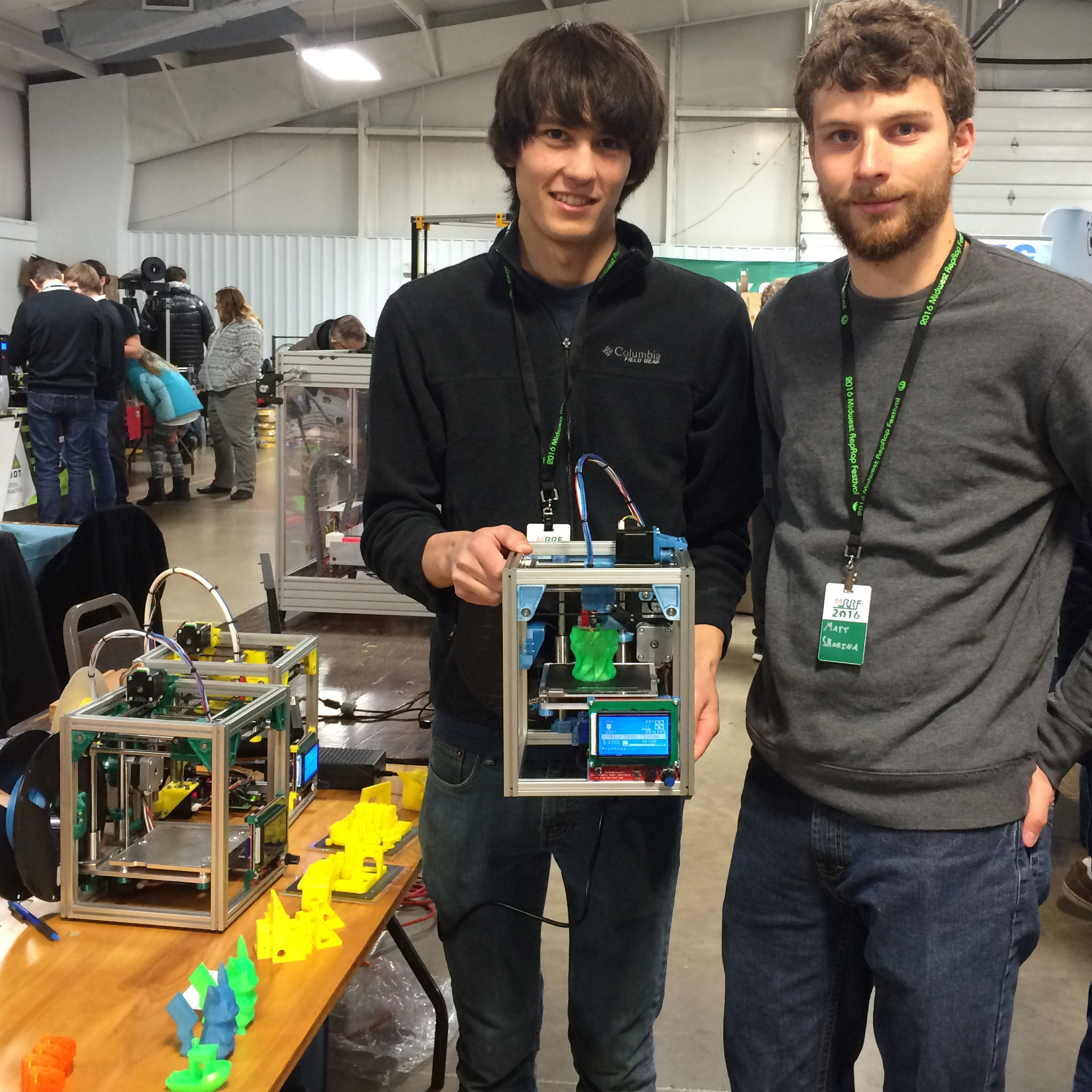
Patrick and Matt hold a running Kitten Printer. The frame is stiff enough that the printer can be held or turned upside down and it can keep printing without visible defects in the print.
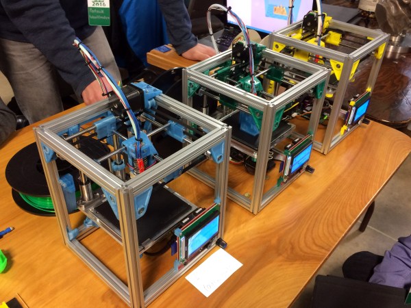
[Patrick] and [Matt] have been coming to the Midwest RepRap Festival from Minneapolis for the past few years and bringing their trusty Tantillus printers with them. However, sometime between this year and the last [Patrick] decided that it would be really fun to make his own 3D printer, and liking the size and accuracy of the Tantillus, started there.
The adorably sized printer is adorably named too: Kitten 3D printer. The printer is certainly an enthusiast’s choice. It’s expensive at 1200 and small, but very well made. Its one big advantage? It prints really accurate parts.
The Tantillus also printed well, but the extruder left a lot to be desired, and the low stretch fishing line movement was very difficult to get tensioned just right. The secret behind the Tantillus and Kitten’s great print quality, aside from good design, is the small xy movement and low weight of the extruder set-ups. By having a movement over a very small range, cumulative errors in construction never get to add up. Also vibrations are less likely to show and smaller moments on the joints mean less flex at the extremes of the movements.
Really stunning print quality almost entirely free of ringing and z-wobble. 100mm x 100mm tray. These are very small parts.
[Patrick] is a mechanical engineer for his day job, and since this was a just for fun printer, he cut no corners. The frame is made with Misumi extrusions and linear movements. The build plate sits on a machined aluminum plate. It’s not flexing or going anywhere.
Part of what really stood out to me about the printer are a lot of neat little features which show careful thought. For example, the extruder movement sits neatly under one of the motors. All the parts except for one can be printed inside its build envelope without support. It uses around 200g of plastic. Every axis is constrained just enough, rather than the common tendency to over constrain that plagues 3D printer design. The spec sheet reads like my printer part wishlist: Bondtech extruder, Rambo board, E3d nozzle, heated bed, flat borosilicate build plate, name brand linear movements, and a well designed Z.
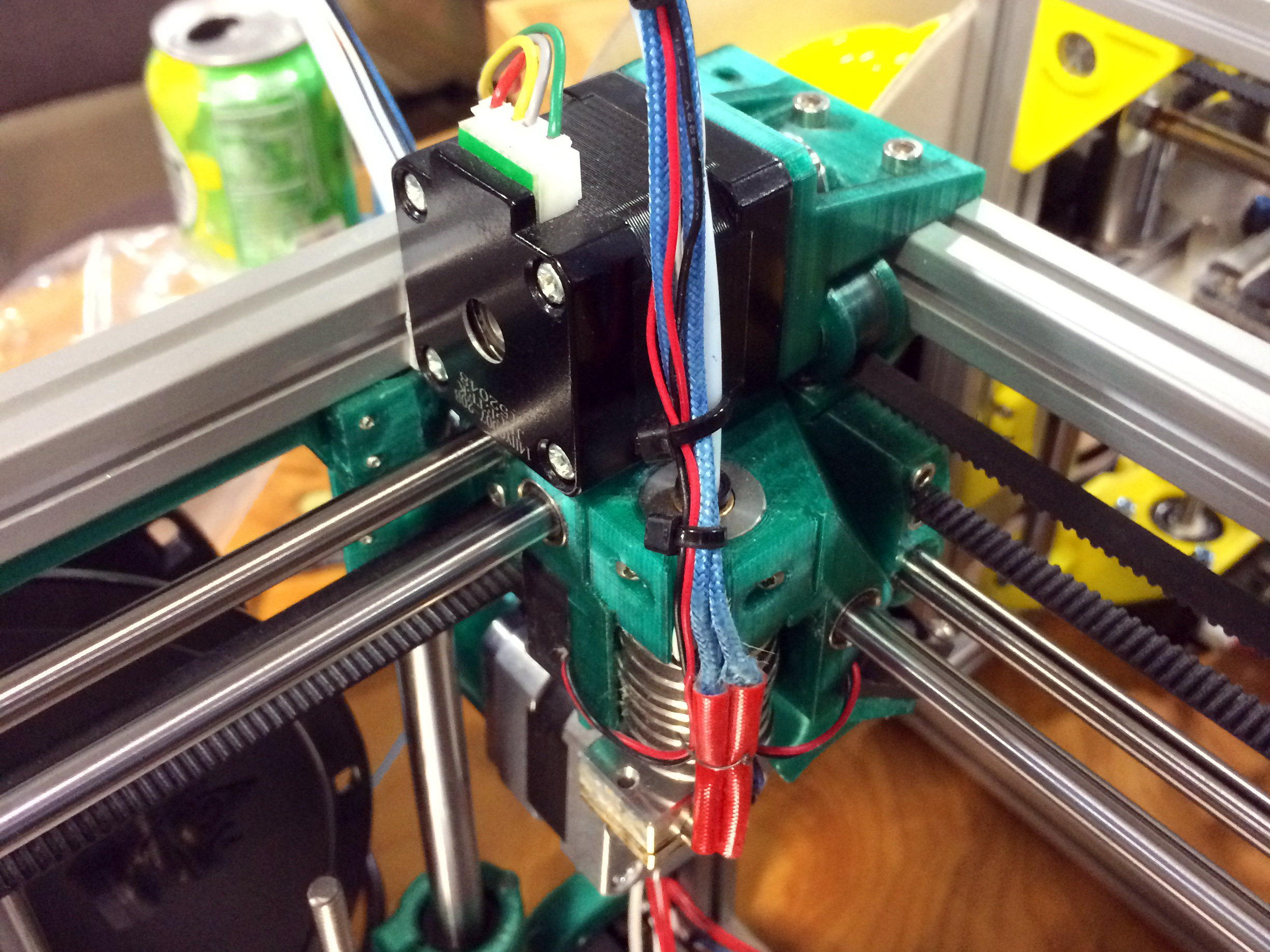
The entire extruder assembly tucks under one of the XY motors at the corner of its movement. Compare its size to the size of a NEMA14 stepper motor.
Another interesting aspect of the design is the extremely light extruder assembly. The lighter an extruder can get, the less ringing will show in your parts at speed. This is one of the most compact designs I’ve witnessed. It consists of two fans, an E3d v6 lite nozzle, and two small linear bearings. The cold end is handled by a bowden set-up and a Bondtech extruder at the back of the printer. The only way to get it lighter would be a different nozzle, such as the upcoming insanely light 13g Pico from B3 unveiled at the festival. I was also interested to see that the bearings on the supporting rails were printed bushings to keep the weight even lower. [nop head] has tested these extensively, they should be fine as long as the rods have a good finish.
I’ve mentioned the size before, but it’s hard to grasp just how adorable this printer is without seeing it. The build envelope is 100mm x 100mm x 100mm, the printer itself is 200mm x 200mm x 240mm. That’s only 50mm wider than the build footprint. It’s a really fun design just to look at and see how they fit it all in there. There are lots of neat little tricks with belt routing and part design to get it all right.
For the enthusiast this would make a good small parts printer and travel printer. However, for me, it was neat to see people still setting out to try designing their own printer. In some ways the 3d printer movement has become crowded with Chinese knock-offs, and I was excited to see something new at the festival. It wasn’t the only new printer design there, but it stood out to me the most. I like the uncompromising nature of it, many people try to design for the lowest BOM and not the nicer print. There are still lots of low-hanging fruit in the 3d printer world and many of them are just getting the mechanics right.
PLA Bushing
Seriously serious Z.
[Patrick] and [Matt] came to the festival with their printer to see if people would like it. They didn’t have grand dreams of selling tons of printers and making millions. They were quite aware that their price point and the small size made it not for everyone. However, their table always had a small crowd. They just really like 3D printers, and that honesty resonated. They didn’t even have a website up at the start of the convention, but by the end they had gotten so many requests they had to oblige. They expect to have 3 kit options available by the end of April. If you’re interested there’s a mailing list sign up on their website. Let’s hope we see them at MRRF again next year with another cool design to look over.
For the last few years, we’ve been going to the Vintage Computer Festival East in New Jersey. This is one of the best cons we go to every year; there are dozens of interesting exhibitors, awesome talks, a great venue, and a small consignment area filled with the weirdest stuff you can imagine. This year proves to be no different, and we’ll be there cataloging the weirdness and spectacular hacks of computer systems old enough to vote, plus something new.
Hackaday’s 8-bit game programming contest is happening for the first time at VCF East, April 15-17 in Wall, New Jersey. Competitors are given two and a half hours and an old 8-bit system (Apple II, C64, Atari 800, etc.). The goal is to create a game using only what is currently in memory, be that in the ROM or between the ears. There are two sessions on the Friday of the event, starting at 10am and 2:30pm.
You can call the 8-bit game programming contest a hackathon. That’s basically what it is; getting a small team together to whip up an application quickly with a number of constraints. The term ‘hackathon’ has been bastardized as of late, with companies requiring the use of a particular API or other nonsense. The 8-bit programming contest doesn’t have these limitations. All you need to do is create the coolest game in two and a half hours, and get the most applause from the audience. The best game wins a prize.
Of course, we’re not going to VCF East just to promote a retro hackathon. We’re only obliged to mention that first because we’re sponsoring it. VCF East is a fantastic event, with more retro goodies to satiate even the most curmudgeonly retro aficionado. The show is enormous with keynotes from [John Blankenbaker], inventor of the Kenbak-1 personal computer and [Stewart Cheifet], host of Computer Chronicles. Dr. Dr. Ted Nelson, author of Computer Lib and creator of Xanadu, the underlying software for computers that won’t be built for 100 years, will also be there. The weekend is, as always, packed with great exhibits of ancient tech, classes, and workshops.
Each Vintage Computer Festival is different, but if you’d like a sample of what it’s all about, check out these posts:
Apart from an announcement for the festival in New Jersey, there are a lot of changes in the organization of the various vintage computer festivals held around the country. The Vintage Computer Festival East was formerly organized by MARCH, the Mid-Atlantic Retro Computing Hobbyists. Late last year, MARCH was dissolved, and reformed as a 501(c)3 called the Vintage Computer Federation. The VCF (see what they did there?) also has the rights to hold VCF West, which last happened in 2007. The VCF Midwest, Southwest, Europe, and UK will remain independent.
If it isn’t already extremely obvious, this is one of the top-tier events we go to every year. No, it’s not DEF CON, it’s not HOPE, and it’s certainly not a big con. It’s just a bunch of nerds nerding out, which is the critical ingredient for the best events we attend all year.
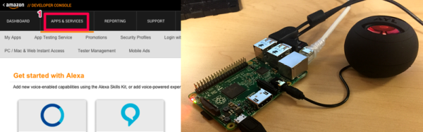
Speech recognition coupled with AI is the new hotness. Amazon’s Echo is a pretty compelling device, for a largish chunk of change. But if you’re interested in building something similar yourself, it’s just gotten a lot easier. Amazon has opened up a GitHub with instructions and code that will get you up and running with their Alexa Voice Service in short order.
Whichever way you slice it, there seems to be a real interest in having our machines listen to us. It’s probably time for an in-depth comparison of the various options. If you know of a voice recognition system that runs on something embeddable — a single-board computer or even a microcontroller — and you’d like to see us look into it, post up in the comments. We’ll see what we can do.
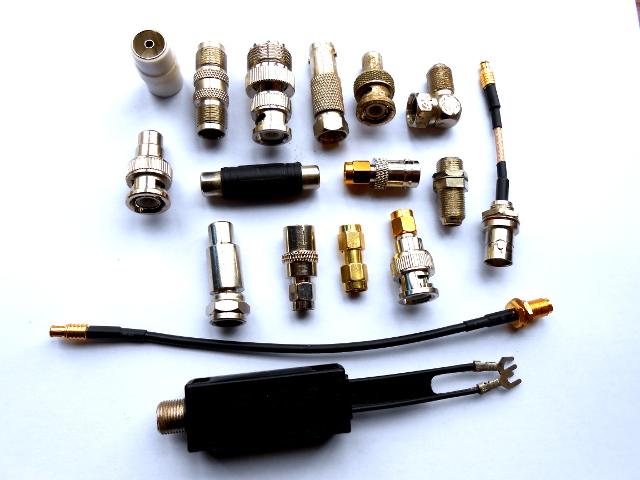
Just a selection from the author’s unholy assortment of adaptors.
If you do any work with analogue signals at frequencies above the most basic audio, it’s probable that somewhere you’ll have a box of coax adaptors. You’ll need them, because the chances are your bench will feature instruments, devices, and modules with a bewildering variety of connectors. In making all these disparate devices talk to each other you probably have a guilty past: at some time you will have created an unholy monster of a coax interface by tying several adaptors together to achieve your desired combination of input and output connector. Don’t worry, your secret is safe with me.
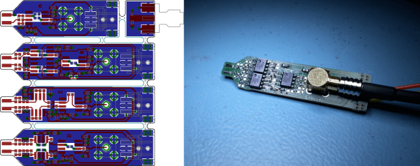
Fancy measurement gear is often expensive to buy, but some bits of kit are entirely DIY’able if you’re willing to put a little work into the project. [Christer Weinigel] needed to get some measurements of a differential clock signal that was ticking away around 500 MHz. El-cheapo probes aren’t going to cut it here. They won’t have the bandwidth and most off-the-rack probes are single-ended, that is they’re referenced to ground. [Christer] needed the difference between two balanced signals, neither of which is grounded. In short, [Christer] needed a high-frequency active differential oscilloscope probe, and they’re not cheap. So he built one himself.
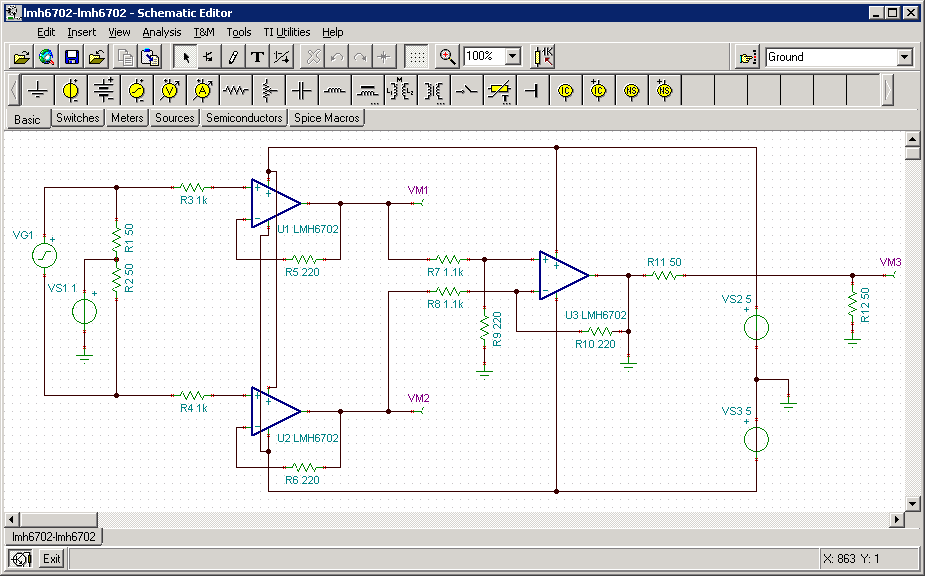
The circuit in the probe is really just an instrumentation amplifier design with a modified input stage and a 50 ohm output impedance. (See this article on in-amps if you need to brush up.) With higher frequencies like this, it’s going to be demanding on the op-amp, so [Christer] spent some time simulating the circuit to make sure it would work with his chosen part. Then he made up a bunch of PCB designs and had them made. Actual results matched fairly well with the simulation.
With some minor tweaking on the input damping resistors, he got a tool that’s dead flat up to 300 MHz, and totally usable up to 850 MHz. If you tried to buy one of these, it’d set you back the cost of a few hundred lattes, but this one can be made for the price of one or two if you get the PCBs done cheaply. Of course, the design files are available for your own use. Kudos [Christer].
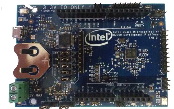
Intel have a developer board that is new to the market, based on their Quark (formerly “Mint Valley”) D2000 low-power x86 microcontroller. This is a micropower 32-bit processor running at 32MHz, and with 32kB of Flash and 8kB of RAM. It’s roughly equivalent to a Pentium-class processor without the x87 FPU, and it has the usual impressive array of built-in microcontroller peripherals and I/O choices.
The board has an Arduino-compatible shield footprint, an FTDI chip for USB connectivity, a compass, acceleration, and temperature sensor chip, and a coin cell holder with micropower switching regulator. Intel provide their own System Studio For Microcontrollers dev environment, based around the familiar Eclipse IDE.
Best of all is the price, under $15 from an assortment of the usual large electronics wholesalers.
This board joins a throng of others in the low-cost microcontroller development board space, each of which will have attributes that its manufacturers will hope make it stand out. Facing such competition the Intel board will have to be something rather special to achieve that aim, so why should it excite your interest? We would point to the low price, the x86 code if that is your flavour of choice, and the relatively tiny power consumption.
Stepping back from the dev board for a moment, consider this processor as an illustration of technological progress in semiconductor fabrication. Over twenty years ago this chip’s Pentium ancestor ran on 5 volts and got so hot you could fry an egg on it, here is a Pentium that can run on a few milliwatts from a coin cell. Fortunately you won’t be running Windows 95 on it though.