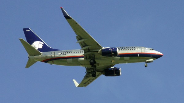
It’s fair to say that 2019 has not been a good year for the aircraft manufacturer Boeing, as its new 737 MAX aircraft has been revealed to contain a software fault that could cause the aircraft to enter a dive and crash. Now stories are circulating of another issue with the 737, some of the so-called “Pickle forks” in the earlier 737NG aircraft have been found to develop cracks.
It’s a concerning story and there are myriad theories surrounding its origin but it should also have a reassuring angle: the painstaking system of maintenance checks that underpins the aviation industry has worked as intended. This problem has been identified before any catastrophic failures have occurred. It’s not the story Boeing needs at the moment, but they and the regulators will no doubt be working hard to produce a new design and ensure that it is fitted to aircraft.
The Role of the Pickle Fork
For those of us who do not work in aviation though it presents a question: what on earth is a pickle fork? The coverage of the story tells us it’s something to do with attaching the wing to the fuselage, but without a handy 737 to open up and take a look at we’re none the wiser.
Fortunately there’s a comprehensive description of one along with a review of wing attachment technologies from Boeing themselves, and it can be found in one of their patents. US9399508B2 is concerned with an active suspension system for wing-fuselage mounts and is a fascinating read in itself, but the part we are concerned with is a description of existing wing fixtures on page 12 of the patent PDF.
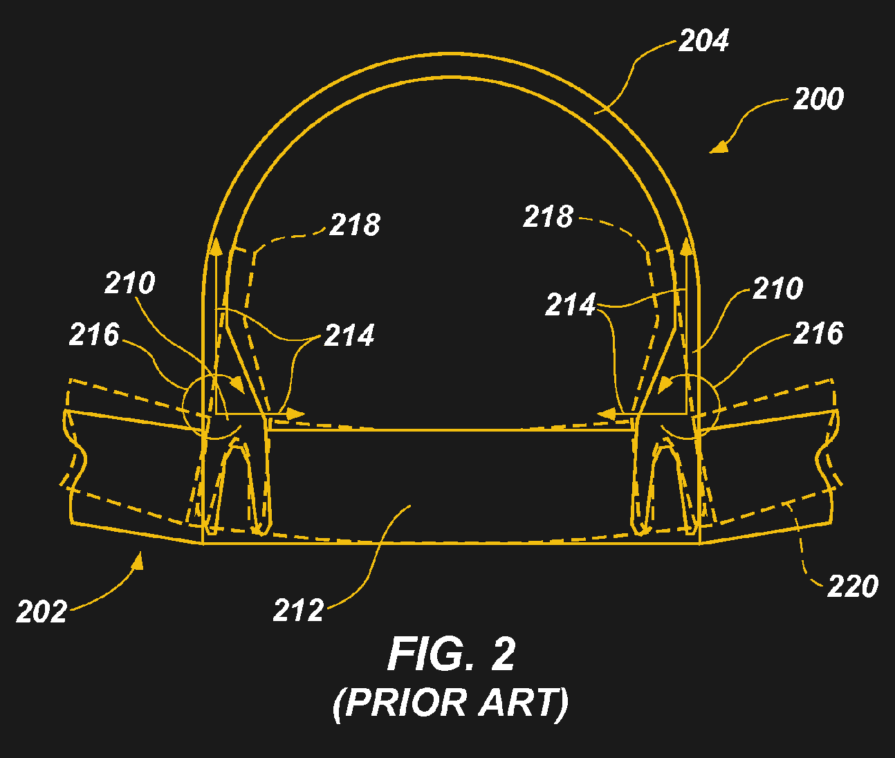
The pickle fork is an assembly so named because of its resemblance to the kitchen utensil, which attaches firmly to each side of the fuselage and has two prongs that extend below it where they are attached to the wing spar.
For the curious engineer with no aviation experience the question is further answered by the patent’s figure 2, which provides a handy cross-section. The other wing attachment they discuss involves the use of pins, leading to the point of the patented invention. Conventional wing fixings transmit the forces from the wing to the fuselage as a rigid unit, requiring the fuselage to be substantial enough to handle those forces and presenting a problem for designers of larger aircraft. The active suspension system is designed to mitigate this, and we’d be fascinated to hear from any readers in the comments who might be able to tell us more.
We think it’s empowering that a science-minded general public can look more deeply at a component singled out in a news report by digging into the explanation in the Boeing patent. We don’t envy the Boeing engineers in their task as they work to produce a replacement, and we hope to hear of their solution as it appears.
[via Hacker News]
[Header image: AMX Boeing 737 XA-PAM by Jean-Philippe Boulet CC-BY 3.0]