So you’ve been rocking a tin foil hat for years now, and people have finally gotten used to your attire and claims that fluoridated water is a government mind control experiment. This holiday, how about something a little more stylish? Yes, it’s a Kickstarter for the World’s First Signal Proof Headwear. This fashionable beanie or cap protects you from harmful electromagnetic rays. Next time you shoot an eighteen minute long YouTube video of a wheezing rant about chemtrails, look fashionable with Shield – the world’s first stylish signal proof hat.
That last tip came to us from a Crowdfunding marketing agency. That means money was exchanged for the purposes of marketing a modern tin foil hat.
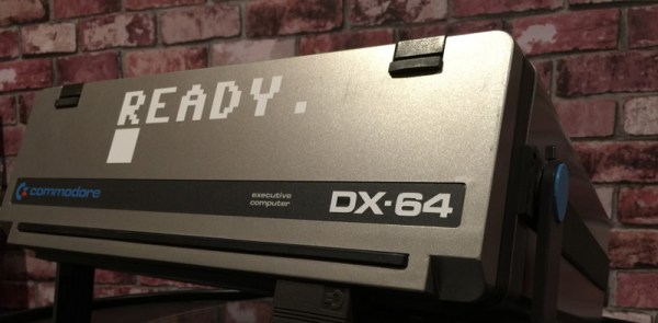
[Mike] has an old IBM 5155, the ‘luggable’ computer with design cues taken from the first Compaq. With an Ethernet adapter and a little inspiration, He was able to get this old computer to load the Hackaday retro edition.
[gyrovague] has a Chromecast that’s a bit janky. When it comes to electronics, strangeness means heat. The solution? A heat sink for the Chromecast. You don’t even need a proper heat sink for this one – just epoxy a big ‘ol transformer to the aluminum plate in the Chromecast.
This year, Keysight gave away a pile of test and measurement gear to the i3Detroit hackerspace. Keysight is doing it again, with a grand prize of around $60,000. Entries close on the 15th. Protip: you, personally, don’t want to win this for tax reasons. A non-profit does.
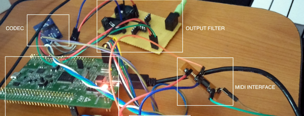
The Internet recently caught wind of a satellite modem being sold by Sparkfun. It’s $250 for the module, with a $12/month line rental, and each 340 byte message costs $0.18 to receive. Yes, it’s cool, and yes, it’s expensive. If you ever need to send a message from the north pole, there you go.
Need to remove the waterproof coating from LED strips? Don’t use a knife, use a Dremel and a wire brush.
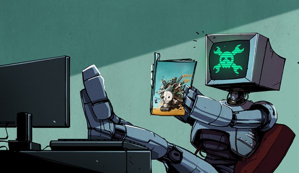
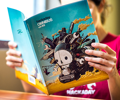 Inside the second edition of the Hackaday Omnibus is 128 pages of actual, real content. There are zero ads, no sponsored content, and absolutely nothing that tells you to go out and buy something. Opening it is an experience unlike anything. Where can you read something for minutes at a time with no interruptions, no email, no Twitter, no Facebook, no text messages, and no ads? You won’t find something like this anywhere else.