It’s great to build projects just to do something neat, to learn; to impress friends and other hackers. It’s even better to address a real need.
I’ve worn hearing aids for 40 some years. My response to the question “Can you hear me now?” is still all too often, “No.” Because of this I heartily applaud the Aegis Acoustics Headset currently active on Kickstarter. I’m happy to see it’s blown through its goal with over a month left.
The Aegis is targeted at prevent hearing loss, primarily in teens since they use headsets so often. It’s equally applicable to adults and pre-teens. The Aegis works by limiting the sound level emitted to 85db, which is a safe level. Above that the risk of damage to the tiny hairs in the cochlea – the inner ear – increases dramatically with a 3db increase cutting the safety time in half.
Future’s So Bright I’ve Got to Wear ‘Aids
My personal experience explains why this is important. At my first professional level job as a software developer I noticed that people at the other end of the table often mumbled during meetings. Not really, because everyone else understood them fine. I needed hearing aids.
My first hearing aids were analog devices. There were three frequency bands across the audio spectrum whose volumes could be custom set for my ears — resulting in crude and limited improvements in what I could hear. My current hearing aids are technological marvels of digital signal processing with a multitude of algorithms the audiologist can use to help me hear better. They even coordinate their actions by communicating between themselves.
I still need to ask people to repeat what they say at times. But who doesn’t? I had a successful career despite my loss. But it is still a royal pain-in-the-butt to miss out on one-third of the dialog in a movie, to not go to a local coffee house because I won’t understand the lyrics or comments by the musicians, and miss out on all the other small parts of life along these lines.
Hacking for Hearing
There are a range of areas where hackers could contribute and not just in assisting individuals, like myself, who personally gain from technological assistance.
Consider how the cell phone improved communications in developing countries. Using radio communications the countries avoided the need to string thousands of miles of wires. That saved the expense and the decades of construction time. It’s easier to get cell phone service than water in some locations. It’s important to notice that it didn’t come about because of a big plan. It came about as an unseen consequence of a technical development.
“We can rebuild him…we have the technology” is from the opening of an old TV series and movies, “The 6 Million Dollar Man” and has found it’s place in the pop-culture vocabulary. But it rings true. We have the technology. We have the tools. We have the expertise. We’re hackers and builders. We and the technology are all over the place. We’re a solution looking for a problem.
Devices that Extend the Body
All signs point to a coming revolution of devices that protect our bodies and make them work better. The 2015 Hackaday Prize theme is Build Something That Matters and that sentiment is obviously taking hold throughout the hardware hacker movement. The Aegis headphones I mentioned above are one example of preventive devices, but look around and there are many more like the UV-Badge which gives you feedback on safe levels of sunlight for your skin.
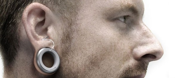
Surely we’re going to see further augmentation for the devices that help restore function. Wearables are all the rage, how long will it be before your smartwatch notification functions make it into my hearing aids? Imagine the improvements we will see in custom hearing profiles born of that smartphone-hearing aid connection. The foundations of this are user-controlled profile switching which is already in place for apps like Belltone’s HearPlus. If the advanced electronics in the smartphone can build a better noise profile and transfer it to the hearing aid my visits to the coffee shop just might get a lot better. And this doesn’t mean the devices need to look the same either. I love the Design Affairs Studio hearing aid concept that is shown at the top of this article. Hardware can be a status symbol after all.
This type of forward thinking easily extends to all assistive technologies such as wheelchair improvements and navigation systems for the blind.
As you look toward your next big hack, roll these concepts around in your mind. The tools, software, and talent have never been easier to connect for our group of citizen scientists who are hacking in basements and garages. It’s exciting to think about the change we can affect using the skills honed over the past decades of this hardware enlightenment we’re all living.