One of the great things about the human intellect is that we have the ability to build machines of varying complexity to do our bidding. As a major proponent of technology, the Chevrolet automobile corporation once dreamed of a future where the American housewife’s most mundane tasks are handled with the push of a button—one that sets a robot butler into action.
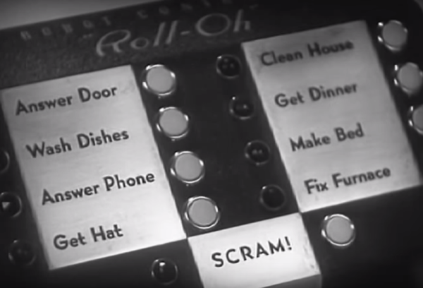
Chevy shows us what this future might look like in this short film, which they presented at the 1940 World’s Fair. A housewife’s faithful ‘robot’, pronounced throughout the picture as ‘robe-it’, has gone on the fritz. Naturally, she calls for a repairman. We see from the console controller that Roll-Oh the Robe-it can take care of all kinds of housewifely duties: he can answer the door and the phone, wash dishes, clean house, make beds, fetch hats, get dinner, and fix the furnace (and only the furnace). And that SCRAM! function? That’s never explained. We like to think it has to do with getting kids off the lawn, or could be used in conjunction with ‘get door’ to chase away would-be burglars. We get a glimpse of this when Roll-Oh answers the door and scares the daylights out of a young [Gary Sinise*] delivering flowers in a cop uniform.
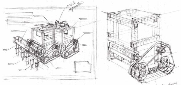
Roll-Oh’s upper limbs have several Swiss Army knife-like implements in them. He uses a sharp one to cut the ribbon off of the flower box. Upon seeing the flowers, he gives them a gentle misting with his sprayer attachment. Dropped petals are no problem for Roll-Oh. He promptly vacuums them up from the thin industrial sound stage carpet with his big metal feet. Roll-Oh is then tasked with getting dinner. This amounts to him painstakingly opening a couple of cans and lighting candles with the torch hidden in his face.
While Roll-Oh the large ductwork butler is only a dream, Chevy wants you to know that smaller robe-its are all around us already. They’re regulating the heat in our stoves, browning our bread without burning it, and brewing our coffee in cool double-globe glass percolators. These tiny servants are capable of performing other tasks, like shutting off machinery when humans are too close, or sensing heat and engaging fire suppression systems. There is brief mention of something called the Petomat, an automatic dog feeding system which is essentially a bowl of food hidden in a latched box. The latch opens rather violently when the alarm clock connected to it goes off.
Robe-its are also performing more serious tasks, like keeping airplanes level and headed in the right direction. Of course, they’re also abundant in Chevrolet automobiles. A small one in the carburetor administers the proper mix of “gasoline calories and fresh air vitamins” to the engine. It’s rare to get to this level of technical detail, you know. Others watch over the spark, the intake manifold, and the voltage regulation. Up in the cab, friendly robe-its will happily traverse the AM dial at the push of a pre-set.
*Probably not actually [Gary Sinise].
Continue reading “Retrotechtacular: Robots, Robots Everywhere, With Kitschy Pronunciation” →