The ability to play music in your car over a Bluetooth connection is very handy. You can typically just leave your phone’s Bluetooth module turned on and it will automatically pair to your car. Then all you have to do is load up a music player app and press play. You don’t have to worry about physically tethering your phone to the car every time you get in and out of the vehicle. Unfortunately Bluetooth is not a standard option in many cars, and it can be expensive to buy an aftermarket adapter.
[parkerlreed] built his own solution to this problem using a Raspberry Pi. He first installed arch Linux on his Pi. He also had to install pulseaudio and bluez, which is trivial if you use a package manager. He then modified some of the Linux configuration files to automatically bring the Pi’s Bluetooth adapter online once it is initialized by the kernel.
At the end of the boot sequence, the Pi is configured to automatically log in to a virtual console as [parkerlreed’s] user. The user’s bashrc file is then altered to start pulseaudio in daemon mode at the end of the login sequence. This allows the Pi to actually play the audio via the Pi’s sound card. The Pi’s stereo output jack is then plugged into the vehicle’s auxiliary input jack using a standard audio cable.
The Reddit post has all of the configuration details you would need to duplicate this setup. [parkerlreed] also includes some commands you will need to setup the initial pairing of the Raspberry Pi to your smart phone. Be sure to watch the video demonstration below. Continue reading “Raspberry Pi Bluetooth Receiver For Your Car Stereo”
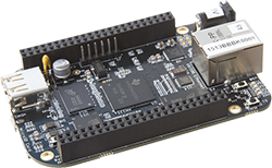 While the BeagleBone is usually compared to the Raspberry Pi, there are a few features that make the ‘Bone a vastly more capable single board computer. There is a small difference in the capabilities of the processor, but the real power of the BeagleBone comes from the PRUs available: two small cores that give the BeagleBone the hardware equivalent of bitbanging pins. [Texane] has put up two great tutorials for using the PRU in the BeagleBone that should be required reading for every BeagleBone owner.