file server

Antique Case For Custom File Server

Michigan Tech was throwing out a bunch of old electronic equipment, and [Evan] snagged quite a gem: a UHF signal generator built by Hewlett Packard circa 1955. He stripped all of the remaining electronics out of the case, but kept the slide-out trays and the front instrument panel to create this antique-looking file server.

The bottom tray was where the bulk of the electronics were housed, and since widespread adaptation of transistors for electronics wasn’t common at the time (the first silicon transistor wasn’t made until 1954), the original equipment was all vacuum tubes. This meant that there was just enough space for a motherboard, heat sink, and a couple of power supplies.

The hard drives are held in custom housings in the top portion of the case. The real magic, however, is with the front display panel. [Evan] was able to use the original meters, including a display for “megacycles” which is still technically accurate. The meters are driven by a USB-to-serial cable and a python script that runs on the server.

The antique case is a great touch for this robust file server. Make sure to put it in a prominent place, like next to your antique tube radio.

THP Quarterfinalist: Low-Cost Solid State Cosmic Ray Observatory

There are a number of crowdsourced projects to put data from around the world onto the Internet, tracking everything from lightning to aircraft transponders. [aelias36]’s entry for The Hackaday Prize is a little different. He’s tracking cosmic rays, and hopes to turn his low-cost hardware into the largest observatory in the world.

Cosmic rays are protons and other atomic nuclei originating far outside the solar system. They hit the very top of Earth’s atmosphere at a significant fraction of the speed of light, and the surface of the Earth is frequently sprayed with particles resulting from cosmic rays. Detecting this particle spray is the basis for all Earth-based cosmic ray observatories, and [aelias] has figured out a cheap way to put detectors in every corner of the globe.

The solution is a simple PIN diode. An op-amp amplifies the tiny signal created in the diode into something a microcontroller can use. Adding a GPS module and an Ethernet connection, this simple detector can send time, position, and particle counts to a server, creating a huge observatory with crowdsourced data.

The detectors [aelias] is working on isn’t great as far as cosmic ray detectors go; the focus here is getting a lot of them out into the field and turning a huge quantity of data into quality data. It’s an interesting project, and the only one with this scale of crowdsourcing we’ve seen for The Hackaday Prize.

You can check out [aelias]’ entry video below.


SpaceWrencherThe project featured in this post is a semifinalist in The Hackaday Prize.

Continue reading “THP Quarterfinalist: Low-Cost Solid State Cosmic Ray Observatory”

Canon Pixma Printer Frontpanel Library

Re-Using The LCD & Button Assembly From A Broken Inkjet Printer

Inkjet printers are a dime a dozen. You probably have taken old printers apart to scavenge parts like motors, pulleys, belts, switches, linear rods, power supply, etc. These parts are easy to reuse in other projects, unlike the controller portion of the printer which not as easy to make use of. [Blaupause] has done something very interesting, and it probably ranks in the ‘extreme difficulty’ category for most tinkerers. He has taken the front panel off an otherwise non-working Canon Pixma inkjet printer and has figured out a way to interface with it.

The front panel of this printer has the standard buttons that you would find on any ole printer, but the Pixmas also has a small LCD screen. [Blaupause] has written a library for the Olimexino microcontroller that can communicate with and make use of the repurposed front panel. And the neat part of this project is that the front panel’s on-board processor does the heavy lifting when it comes to displaying images on the LCD screen or checking button states which frees up your microcontroller to do whatever else. Right now, the LCD screen can display bitmaps and supports image transparency. The library can not display video as of yet, but that option is being worked on.

[Blaupause] makes all his hard work available to the public on the project’s Sourceforge page. In addition to the library, he also includes printer panel pinouts and detailed information on how to communicate with the buttons and LCD screen. Video after the break…

Continue reading “Re-Using The LCD & Button Assembly From A Broken Inkjet Printer”

The Walking Dead Survival Box For The Zombie Apocalypse 

When the world comes to an end and zombies run through the streets like a blood thirsty disease, it will be absolutely necessary to store a weapon (or five) away just in case an undead creature tries to get inside. In addition, stopping crooks from ransacking back up supplies will also be a primary concern as well as savage, brain-eating beasts take over the cities. Keeping objects safe with a lock box like this one would deter both undead creatures and mischievous thieves. Or at least that is what was going on in [Mattt Reamer’s] head when he took on this build.

[Matt] is a UX designer who drew inspiration from the wildly popular television series The Walking Dead. He even 3D printed the Walking Dead’s logo on the front of the blood stained box attributing the idea to the show.

The setup here uses an Arduino Uno which is powered by a 9-Volt battery. The fingerprint scanner unlocks the box by verifying the print against a reverence copy stored in the code. When the program authorizes the scan, a servo opens up the latch allowing the contents within to be retrieved. Video of the full system can be seen after the break.

Now all that comes next would be to protect those fingers.

Continue reading “The Walking Dead Survival Box For The Zombie Apocalypse “

THP Hacker Bio: Peter McCloud

By far one of the craziest entries for The Hackaday Prize is [Peter McCloud]’s Goliath, an enormous gas-powered quadcopter. It weighs about 240 pounds, is powered by a 30 horsepower v-twin lawnmower engine, is lifted into the air with homemade props milled on a CNC machine. It’s a frightening build even when the engine isn’t turning. When running, it’s an awesome display of power and technology.

Goliath has had a few setbacks of late, snapping two composite props in its first attempt at hovering. This hasn’t deterred [Peter]; he’s picking up the pieces and he’ll have this monstrous quad hovering in a week or two. A good thing, because the judges are paring the quarterfinalists just three weekends from now.

Check out [Peter]’s bio below.

Continue reading “THP Hacker Bio: Peter McCloud”

WS2812 at 670 kHz

Driving WS2812B Pixels, With DMA Based SPI

Typically bit-banging an I/O line is the common method of driving the WS2812B (WS2811) RGB LEDs. However, this ties up precious microcontroller cycles while it waits around to flip a bit. A less processor intensive method is to use one of the built-in Serial Peripheral Interface (SPI) modules. This is done using specially crafted data and baud rate settings, that when shifted out over the Serial Data Out (SDO) pin, recreate the needed WS2812B signal timing. Even when running in SPI mode, your hardware TX buffer size will limit how many pixels you can update without CPU intervention.

[Henrik] gets around this limitation by using peripheral DMA (Direct Memory Access) to the SPI module in the Microchip PIC32MX250F128B microcontroller. Once properly configured, the DMA controller will auto increment through the defined section of DMA RAM, sending the pixel data over to the SPI module. Since the DMA controller takes care of the transfer, the micro is free to do other things. This makes all of DMA memory your display buffer. And leaves plenty of precious microcontroller cycles available to calculate what patterns you want the RGB LEDs to display.

Source code is available at the above link for those who would like to peruse, or try it out. This is part of [Henrik’s] Pixel Art Project. Video of DMA based SPI pixels after the break:

Continue reading “Driving WS2812B Pixels, With DMA Based SPI”

Hands On With The Intel Edison

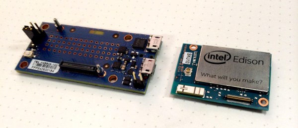
Yesterday the tech world resounded with the astonishing news that Apple can’t run a CMS, rotary encoders were invented just for the Apple Watch, and Intel’s Developer Forum was scheduled well in advance of the Apple media circus. Intel’s smallest computer yet, the Edison, was also announced. Very few people without an Intel employee badge have one of these cool little devices, and lucky for us one of them put up a hands-on review.

With a lot of comments asking what the Edison is good for, [Dimitri] tells us the Edison isn’t meant to be only a dev board. A better comparison would be something like the Raspberry Pi compute module – a small board that product designers can build a device around. This, of course, is not news and should come as a surprise to no one. The 70-pin connector used in the Edison isn’t rated for high-frequency insertions, anyway.

Stock up on level shifters

Compared to even a Raspberry Pi, or even an Arduino Mega, the Arduino breakout board for the Edison is huge. The reason for this is a huge number of level shifters. Where Arduinos can chug right along at 3.3V and 5V, and a Pi uses the somewhat more uncommon (at least for the hobbyist market) 3.3V logic, most of the Edison runs at 1.8V.  All the user-configurable pins on the smaller breakout are 1.8V logic. Someone reading this will fry their Edison, so don’t say we didn’t warn you.

Performance

[Dimitri] was keen to get an idea of how powerful the Edison is. There’s a pretty good chip in there – an Atom Z34XX – that’s underclocked at 500MHz. Still, despite this apparent performance limitation, a few benchmarks reveal the Edison can work at up to 615 MIPS. That’s about twice the performance of the Raspberry Pi B+, and real-world tests of doing FFT along with OpenCV tracking makes [Dimitri] happy. Power consumption? At a medium load, the Edison draws about 200 mA. A lot of number crunching and blasting bits out of the radios increases that to a maximum of 500 mA. Not exactly low power, but very good in terms of performance per Watt.

Wireless

There are two radios on the Edison, one for Bluetooth Low Energy, and another for a/b/g/n WiFi (yes, it supports access mode). The on-chip antenna is acceptable, but for sending signals to the conference room down the hall, you might want to connect an external antenna.

Linux, Programming, and Arduino

Linux on the Edison isn’t a friendly Debian-derived installation like the Raspberry Pi. Instead, Intel is using Yocto, specifically designed for embedded environments. It’s not quite a distribution but instead a build system. There is no apt-get. Right now, this might be seen as a limitation, but enterprising kernel wizards have ported Debian to the Intel Galileo. Full Linux support is coming, but probably not (officially) from Intel.

Edison launched with an Arduino breakout board, but the Arduino compatibility is literally only a facade. Intel reengineered the Arduino IDE so it writes files instead of toggling pins. This means any programming language that can write a file is able to blink a LED with an Edison. It’s only a matter of preference, but if your idea of embedded development is a single chip and a C compiler, you’re better off using an ATMega and a UART.

Closing thoughts

This isn’t a Raspi killer, a Beaglebone killer, a TI CC3200 killer, or an ESP8266 killer. It’s an x86 board, with WiFi, Bluetooth and Linux that can toggle a few pins. It’s something different. Different is good. That means there are more choices.